
Head rest control device and active head rest

a technology of active head rest and control device, which is applied in the direction of chairs, pedestrian/occupant safety arrangements, vehicular safety arrangements, etc., can solve the problems that the active headrest according to patent documents 1 and 2 are sometimes uncomfortable for passengers, and achieve the effect of convenient us

Inactive Publication Date: 2009-11-17
TOYOTA BOSHOKU KK +1
View PDF25 Cites 64 Cited by
  • Summary
  • Abstract
  • Description
  • Claims
  • Application Information

AI Technical Summary

Benefits of technology

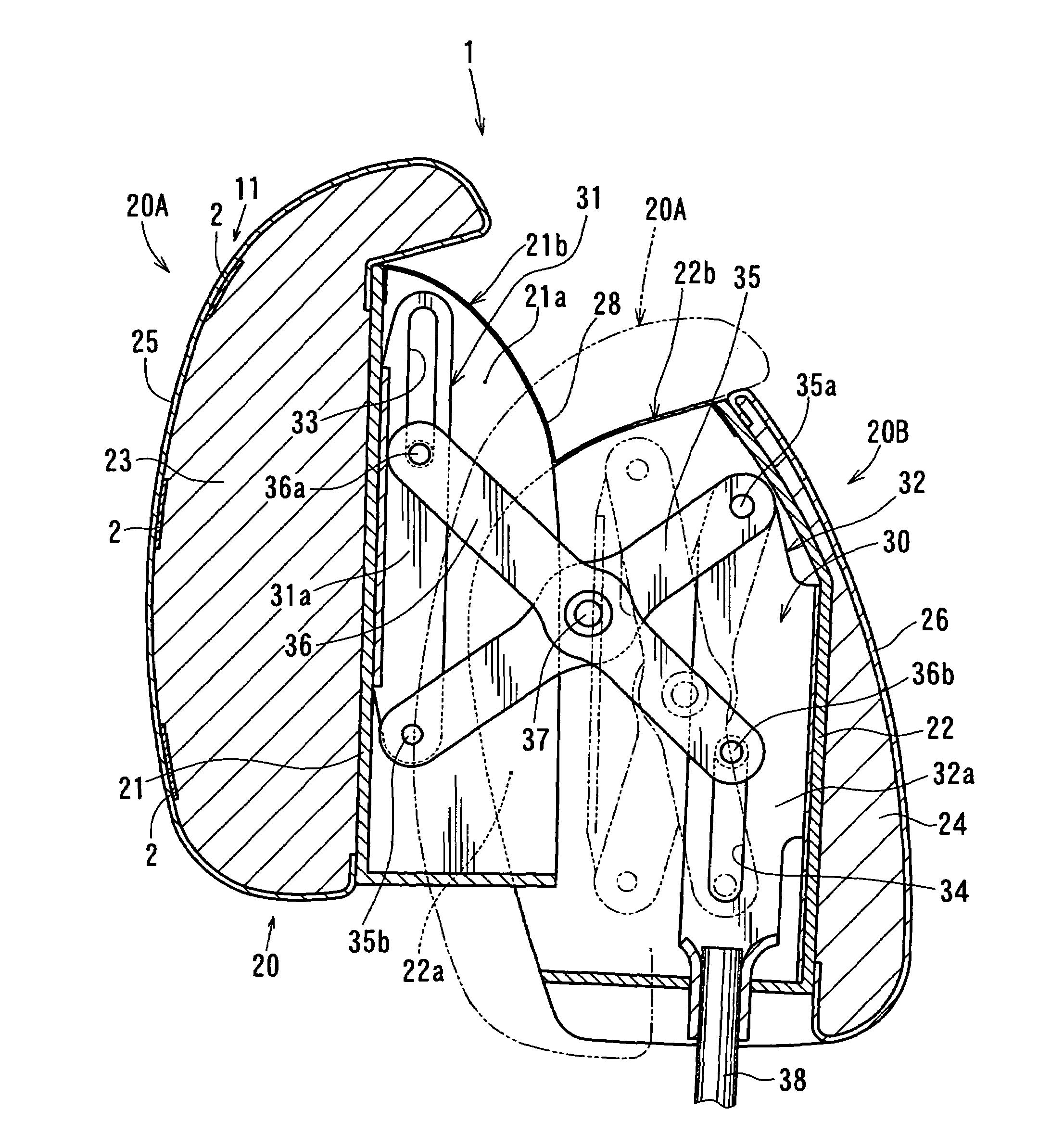
[0012]Therefore, the headrest can be stopped at a proper position in accordance with the position of the head of a passenger. For example, the headrest can be stopped at a position where the head will not be over-pushed.
[0019]It is therefore possible to move the headrest toward the head of the passenger and to stop the headrest at a proper position in accordance with the position of the head of the passenger.
[0025]It is therefore possible to move the front part of the headrest toward the head of the passenger and to stop the front part of the headrest at a proper position in accordance with the position of the head of the passenger. For example, the front part of the headrest can be stopped at a position where the head will not be over-pushed by the front part of the headrest.
[0028]Therefore, the front part of the headrest is automatically returned to the initial position when the forward movement becomes unnecessary, e.g., when no crash has occurred. Since the headrest is thus returned to its normal state, it is easy to use.

Problems solved by technology

As a result, the active headrests according to Patent Documents 1 and 2 have sometimes been uncomfortable for a passenger because the headrests can push the head of a passenger too much.

Method used


Image

  • Head rest control device and active head rest
  • Head rest control device and active head rest
  • Head rest control device and active head rest

Examples


embodiment 3

[0119]Another configuration according to the present invention includes a camera mounted on the ceiling of a cabin and a head position detection unit having a measuring device for measuring the distance between the head of a passenger and a headrest based on a picture from the camera instead of the head position detecting unit 11 shown in FIG. 8.

[0120]This configuration includes a control circuit, which stops the headrest based on a signal from the head position detection unit.

[0121]The present invention is not limited to configurations described above and may be implemented in the following modes.

[0122](1) The active headrests according to Embodiments 1 to 3 are configured to operate based on a detection signal from a crash detecting sensor for predicting a rear crash. Alternatively, an active headrest may include a crash detecting sensor for detecting a rear crash and may be configured to operate based on a signal from the crash detecting sensor.

[0123](2) The head position detecti...


PUM


Abstract

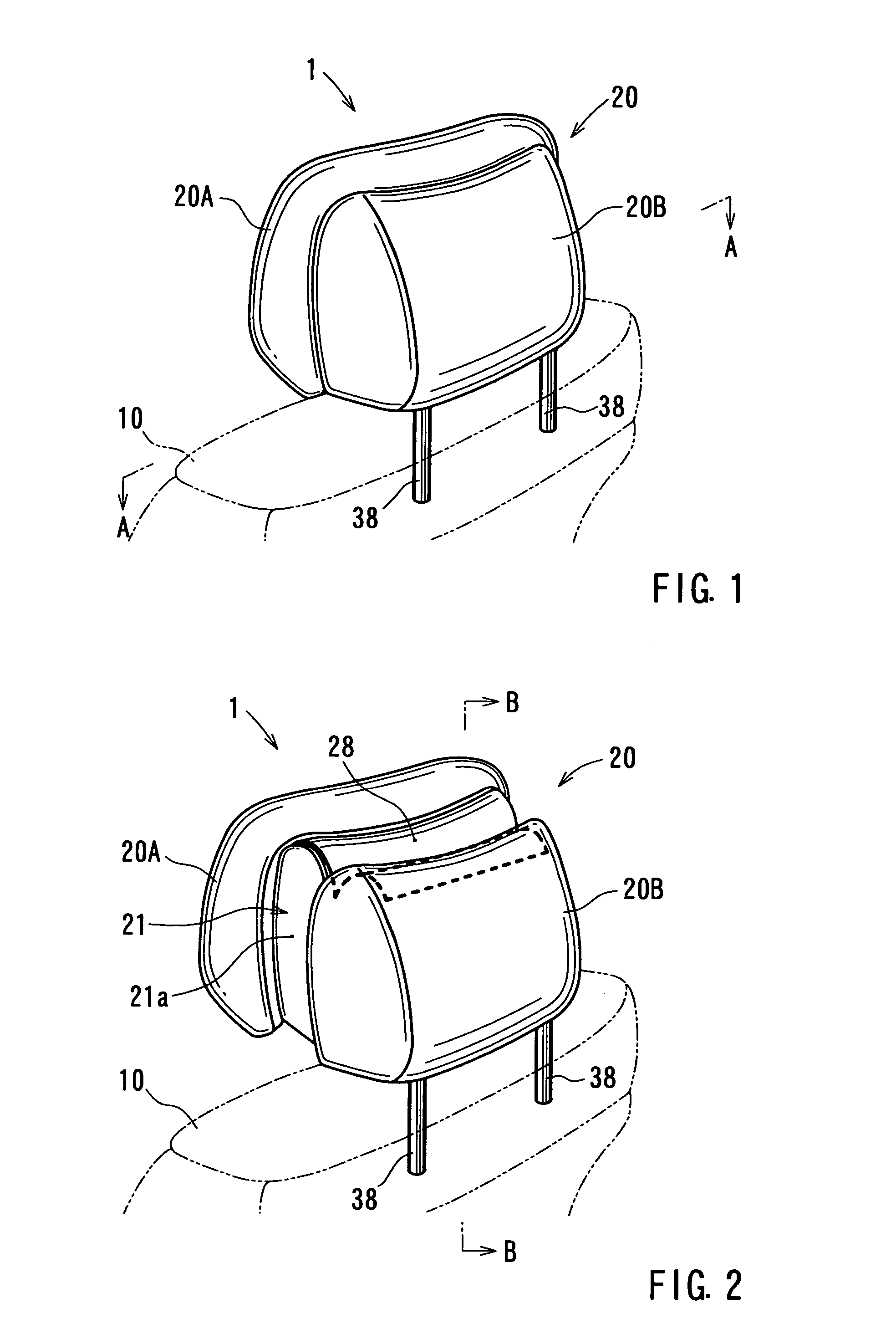
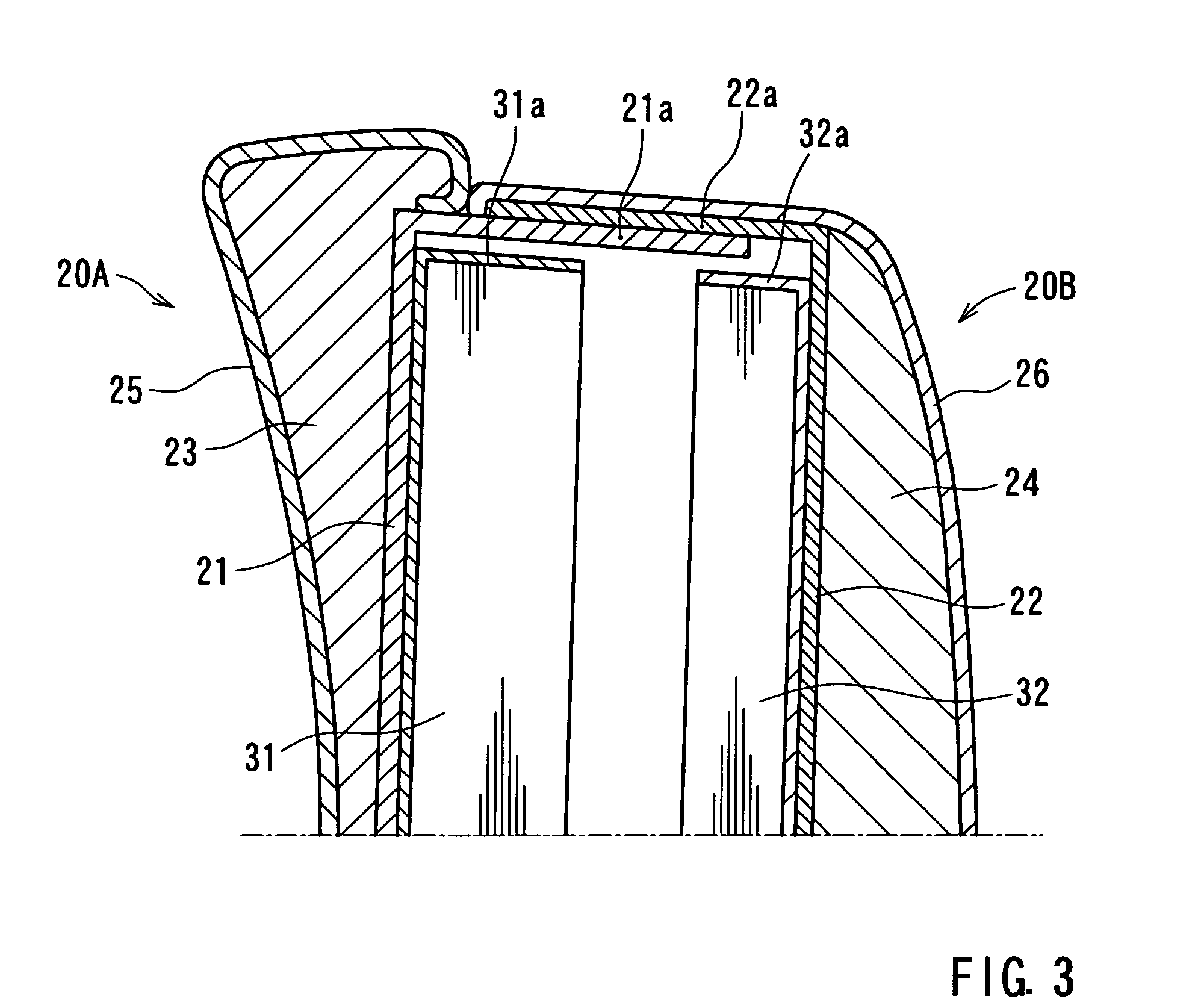
It is an object of this invention to provide an active headrest which will not over-push the head of a passenger. For this purpose, the invention provides a headrest controller for moving a part (20A) or whole of a headrest (20) of a vehicle seat toward a head of the passenger to reduce the distance between the headrest (20) and the head in the horizontal direction by predicting or detecting a crash to the rear of the vehicle, including a head position detecting unit (11) for detecting a predetermined state of approach or state of contact of the headrest (20) to or with the head during the movement of the headrest (20) and a control circuit for stopping the headrest based on a detection signal from the head position detecting unit (11).

Description

TECHNICAL FIELD[0001]The present invention relates to a headrest controller for moving part or whole of a headrest of a seat of a vehicle toward the head of a passenger to reduce the distance between the headrest and the head in the horizontal direction by predicting or detecting a crash to the rear of the vehicle and relates to an active headrest.BACKGROUND ART[0002]Various types of active headrests have been known, and known active headrests include, for example, those disclosed in Patent Document 1 (JP-A-11-334439), Patent Document 2 (JP-A-2004-9891), Patent Document 3 (JP-A-2000-309242), and Patent Document 4 (JP-A-2000-233713).[0003]An active headrest according to an invention disclosed in Patent Document 1 has a configuration in which the headrest is tilted based on a detection signal from a crash detecting sensor for predicting or detecting a rear crash. It is configured such that an abutting surface (a front part) of the headrest is moved toward a passenger and is also tilte...

Claims


Application Information

Patent Timeline
IPC IPC(8): B60N2/48B60N2/00
CPCB60N2/002B60N2/4885B60N2/4861B60N2/888B60N2/862B60N2/0268B60N2/0276B60N2210/12B60N2210/24B60N2220/20B60N2/0028B60N2/42
Inventor AKAIKE, FUMITOSHIMATSUBAYASHI, KIYOKA
Owner TOYOTA BOSHOKU KK
Learn More