Hydraulic tensioner with improved relief valve

a relief valve and hydraulic technology, applied in valve drives, machine/engines, valve drives, etc., can solve the problems of affecting requiring a great deal of time and effort, and the depth of the axial groove or groove formed on the outer surface of the spring-receiving plug is limited, so as to improve the flow of oil, improve the production, and facilitate the integration of the plug into the plunger

Active Publication Date: 2009-11-17
HONDA MOTOR CO LTD
View PDF15 Cites 27 Cited by
  • Summary
  • Abstract
  • Description
  • Claims
  • Application Information

AI Technical Summary

Benefits of technology

[0009]An object of this invention is to provide a relief valve in a hydraulic tensioner, in which relative circumferential displacement of the valve seat and the spring-retaining plug, both of which are press-fit into the plunger, does not materially affect oil flow, or produce variations in tensioner performance. Another object of the invention is to provide for unimpeded flow of oil past the spring-retaining plug without impairing the rigidity and integrity of the plug. Still another object of the invention is to simplify the production of a tensioner and particularly the relief valve spring-retaining plug.
[0014]When the spring-receiving plug has a large diameter portion and a small diameter portion, oil flow is further improved. In addition, since the length of the part of the plug that is press-fit into the plunger is shorter, it is easier to incorporate the plug into the plunger.
[0015]In addition, since the axial flat portions on the outside of the spring-receiving plug may be formed by forging, machining of grooves on the outside of the plug is avoided, production is improved, and manufacturing costs can be reduced.

Problems solved by technology

Thus, flow of oil can be impeded if the seat and plug are installed in such a way that the grooves are not in alignment, and performance of the relief valves can vary.
In addition, the depths of the axial groove or grooves formed on the outer surface of the spring-receiving plug are limited by the requirements for integrity and rigidity in the plug.
Furthermore, the axial grooves in the plug are produced by machining, which requires a great deal of time and effort.

Method used


Image

  • Hydraulic tensioner with improved relief valve
  • Hydraulic tensioner with improved relief valve
  • Hydraulic tensioner with improved relief valve

Examples


Embodiment Construction

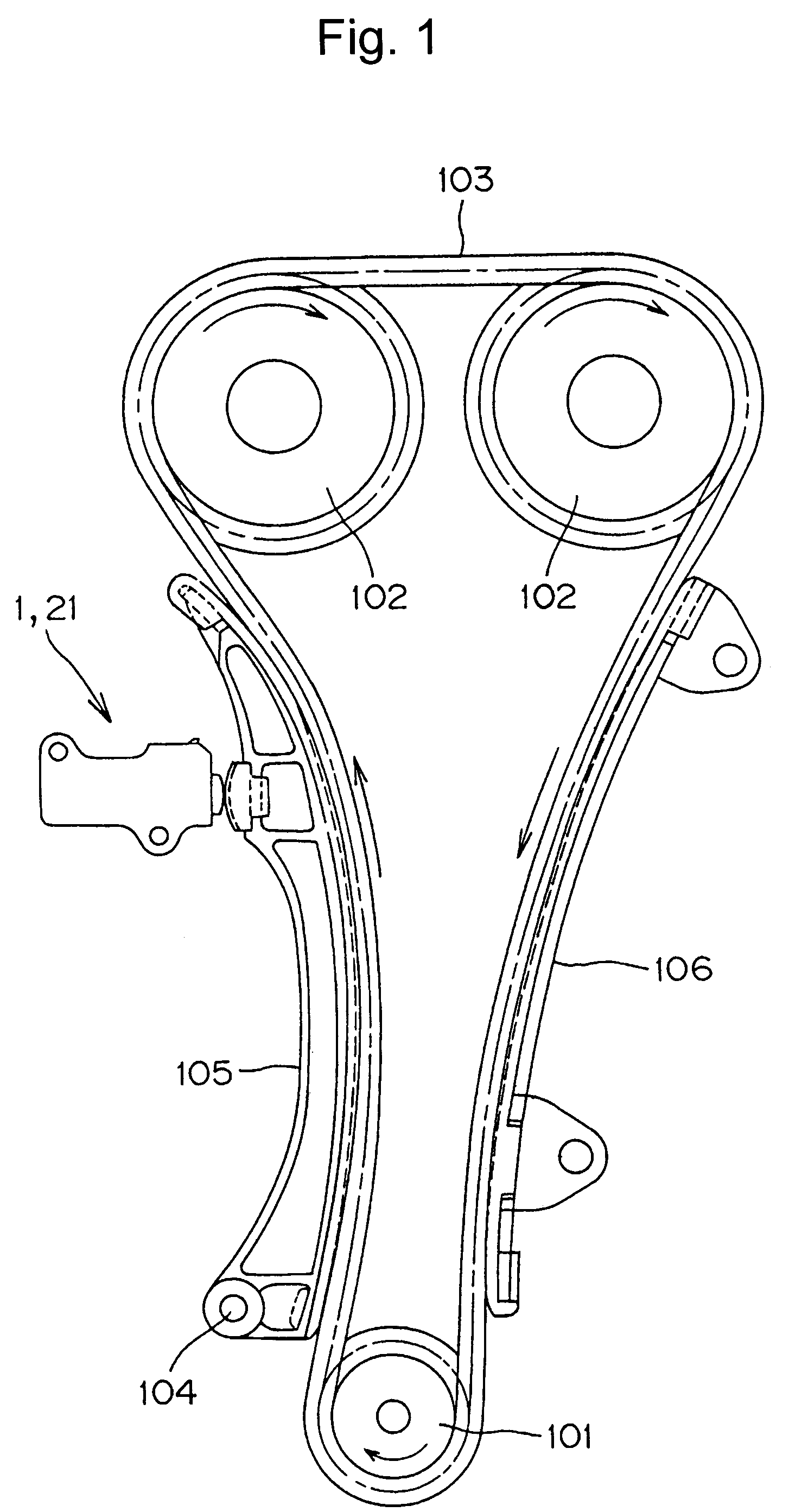
[0025]As shown in FIG. 1, a hydraulic tensioner 1 is attached to an engine block2 adjacent the slack side of a timing chain 103, which is driven by a crankshaft sprocket 101, and in driving relationship with a pair of camshaft sprockets 102. The plunger of the tensioner presses against the back of a lever 105 pivotally supported on a pin 104 attached to the engine block. The plunger of the tensioner applies tension to a timing chain 103 through the lever 105. A guide 106, also attached to the engine block, is in engagement with the return side of the timing chain 103. Arrows in FIG. 1 indicate the direction of travel of the chain and the directions of rotation of the sprockets.

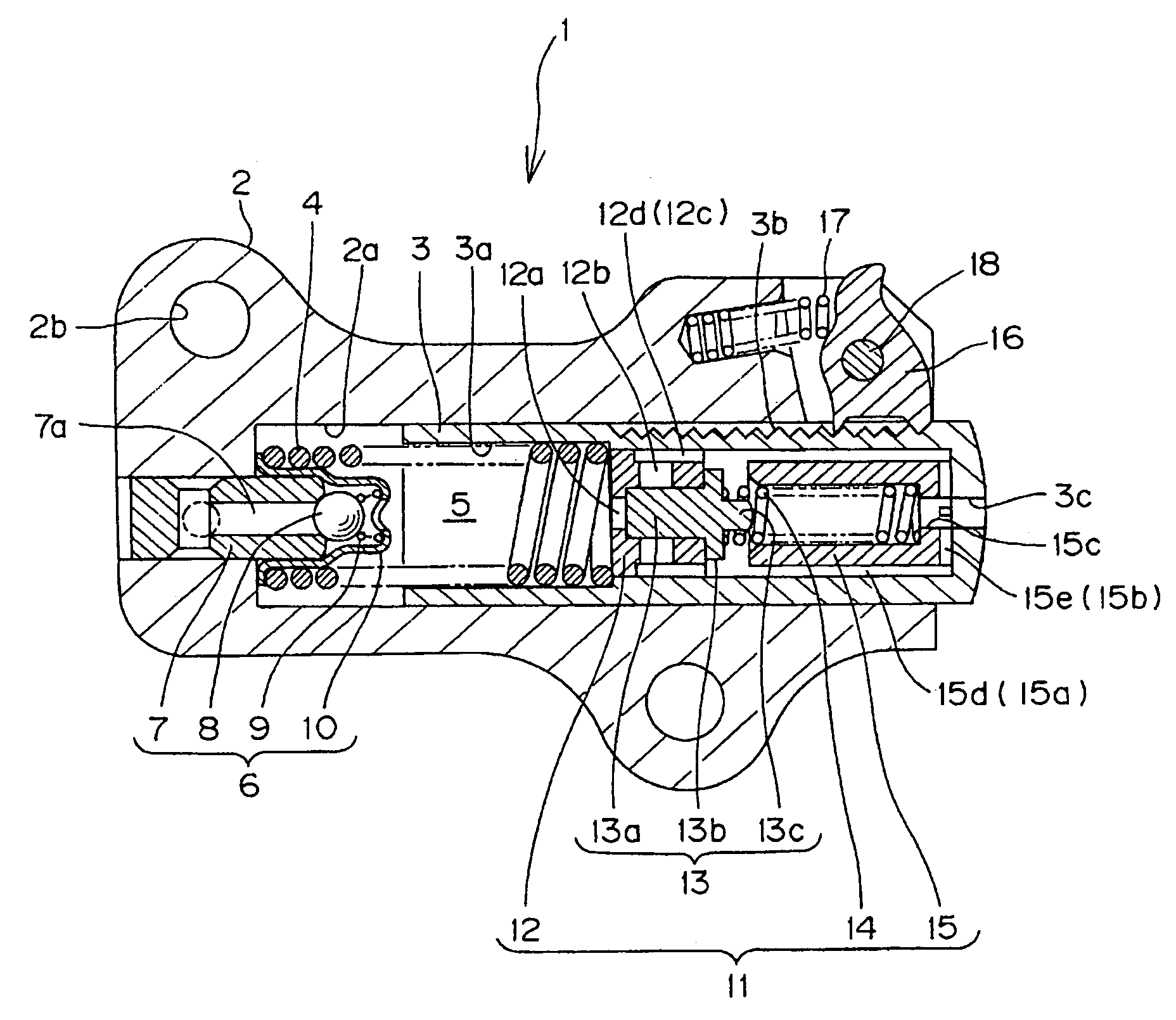
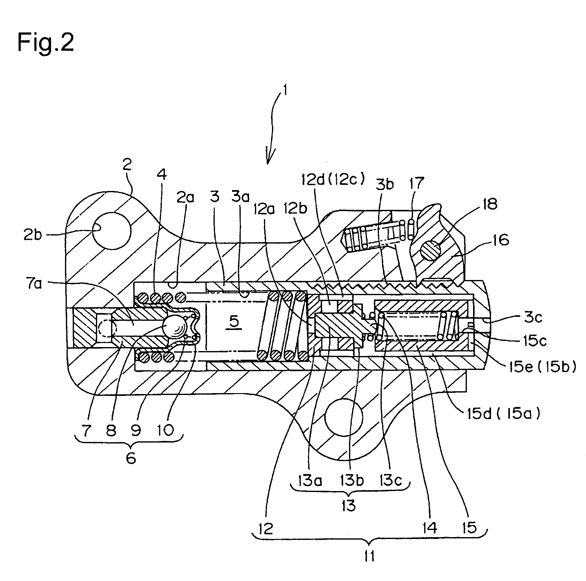
[0026]As shown in FIG. 2, the tensioner comprises a housing 2, a hollow, generally cylindrical, plunger 3 slidably disposed in a hole 2a in the housing and protruding from the housing. The hollow portion has an opening at the end of the plunger inside the housing, and a bottom, formed by the protruding end of ...


PUM


Abstract

In a hydraulic tensioner having a relief valve inside its plunger, a relief valve spring-receiving plug, press-fit into the plunger is formed by forging a plurality of flat surfaces on its exterior. These flat surfaces, in cooperation with the cylindrical inner wall of the plunger, form plural oil passages, each having a segment-shaped cross-section. The oil passages allow flow of oil past the plug to a discharge opening at the front end of the plunger, and the flow of oil is substantially unaffected by circumferential displacement of the oil passages on the periphery of the plug relative to the oil passages on the periphery of the relief valve seat.

Description

FIELD OF THE INVENTION[0001]This invention relates to hydraulic tensioners of the type used for applying tension to a timing chain or the like in a vehicle engine, and more particularly to an improved relief valve in a hydraulic tensioner.BACKGROUND OF THE INVENTION[0002]Tensioners are widely used to maintain proper tension and prevent vibrations in power-transmitting chains. In a typical internal combustion engine timing drive, the tensioner is mounted on the engine, and applies pressure to a pivoted lever which is in sliding contact with the chain, thereby maintaining tension in the chain.[0003]A hydraulic tensioner with a relief valve is described in United States Patent Application Publication No. 2002 / 0052259, published, May 2, 2002. The tensioner comprises a housing, and a hollow plunger, slidable in a hole in the housing, and protruding from the housing. A high pressure oil chamber is formed by the housing and the inside of the plunger. The plunger urged in the protruding dir...

Claims


Application Information

Patent Timeline
Patent Type & Authority Patents(United States)
IPC IPC(8): F16H7/08F01L1/02F01L1/053
CPCF01L1/02F01L1/053F16H7/0836F16H2007/0859F16H2007/0812F16H2007/0814F16H2007/0853F16H2007/0806
Inventor HASHIMOTO, HIROSHIKUROKAWA, YOSHIONAMIE, TSUTOMUIWATA, KAZUYUKI
Owner HONDA MOTOR CO LTD
Why Eureka
Try Eureka