Vane-type demister

a demister and vane-type technology, applied in the field of demisters, can solve the problems of increasing manufacturing complexity, high manufacturing cost in terms of time, skill and materials, and the inability of entrained droplets to negotiate the rapid zig-zag, so as to avoid unacceptable pressure drops and high vapor-liquid separation

Active Publication Date: 2009-11-17
UOP LLC
View PDF32 Cites 67 Cited by
  • Summary
  • Abstract
  • Description
  • Claims
  • Application Information

AI Technical Summary

Benefits of technology

[0012]An advantage of the present invention is that the use of flat sheets and corrugated sheets with louvers are simply layered to form a self supporting separating structure. That is, the layered sheets and fluid flow channels they define are able to maintain the desired spacing without requiring other elements such as spacers, fasteners, and welding. Further, variations of the geometric design of the vanes and louvers of the present invention may be provided to achieve high vapor-liquid separation while avoiding unacceptable pressure drops in dynamically disparate systems.
is that the use of flat sheets and corrugated sheets with louvers are simply layered to form a self supporting separating structure. That is, the layered sheets and fluid flow channels they define are able to maintain the desired spacing without requiring other elements such as spacers, fasteners, and welding. Further, variations of the geometric design of the vanes and louvers of the present invention may be provided to achieve high vapor-liquid separation while avoiding unacceptable pressure drops in dynamically disparate systems.

Problems solved by technology

The vanes and spacers are often welded or bolted into position, which has a high manufacturing cost in terms of time, skill, and materials.
The entrained droplets cannot negotiate the rapid zig-zag and impinge on the vane, where they cling and run down the wall.
The welding, bolting, or otherwise attaching of the louvers, however, increases the complexity of manufacturing.

Method used


Image

  • Vane-type demister
  • Vane-type demister
  • Vane-type demister

Examples


Embodiment Construction

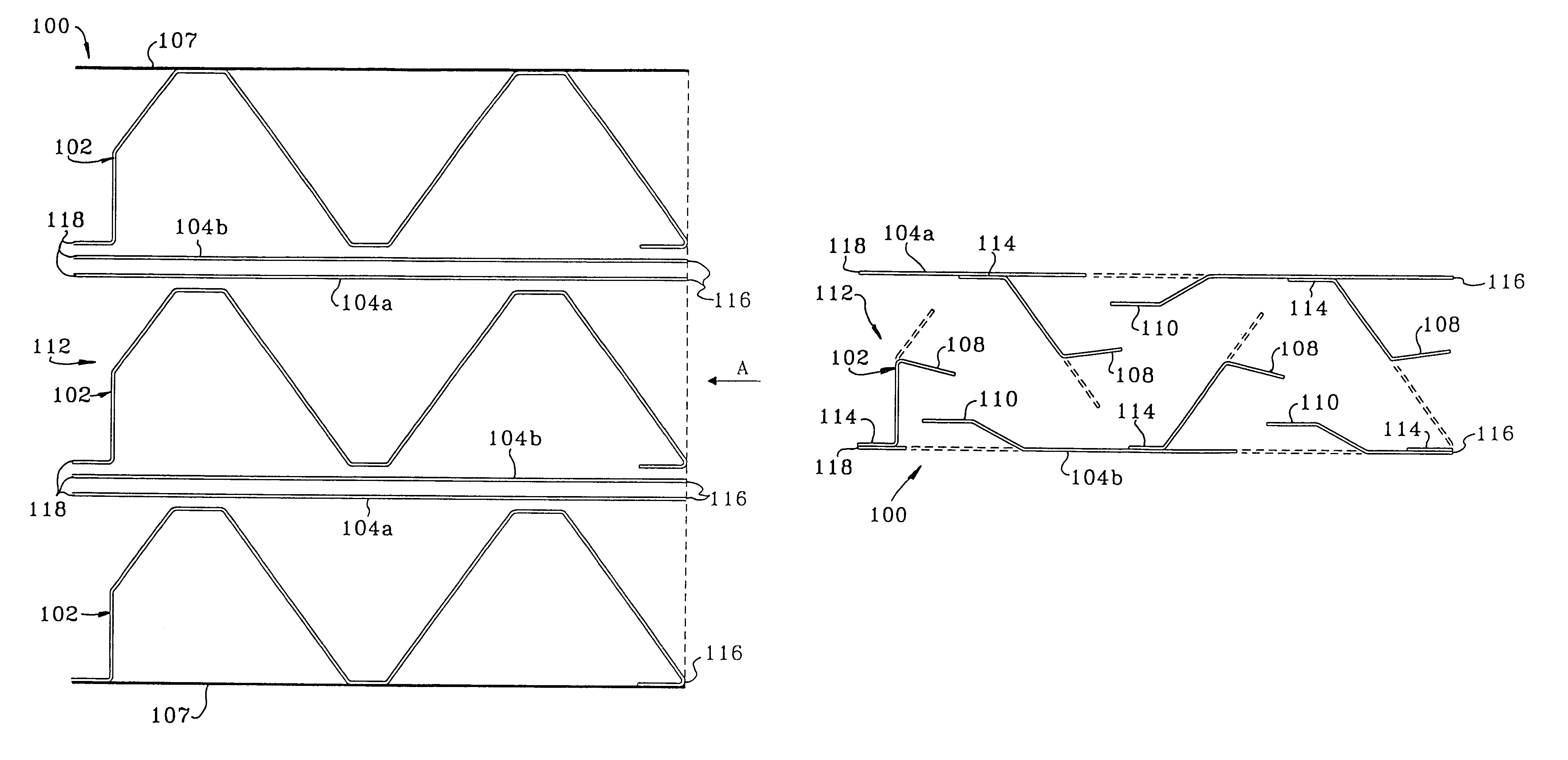
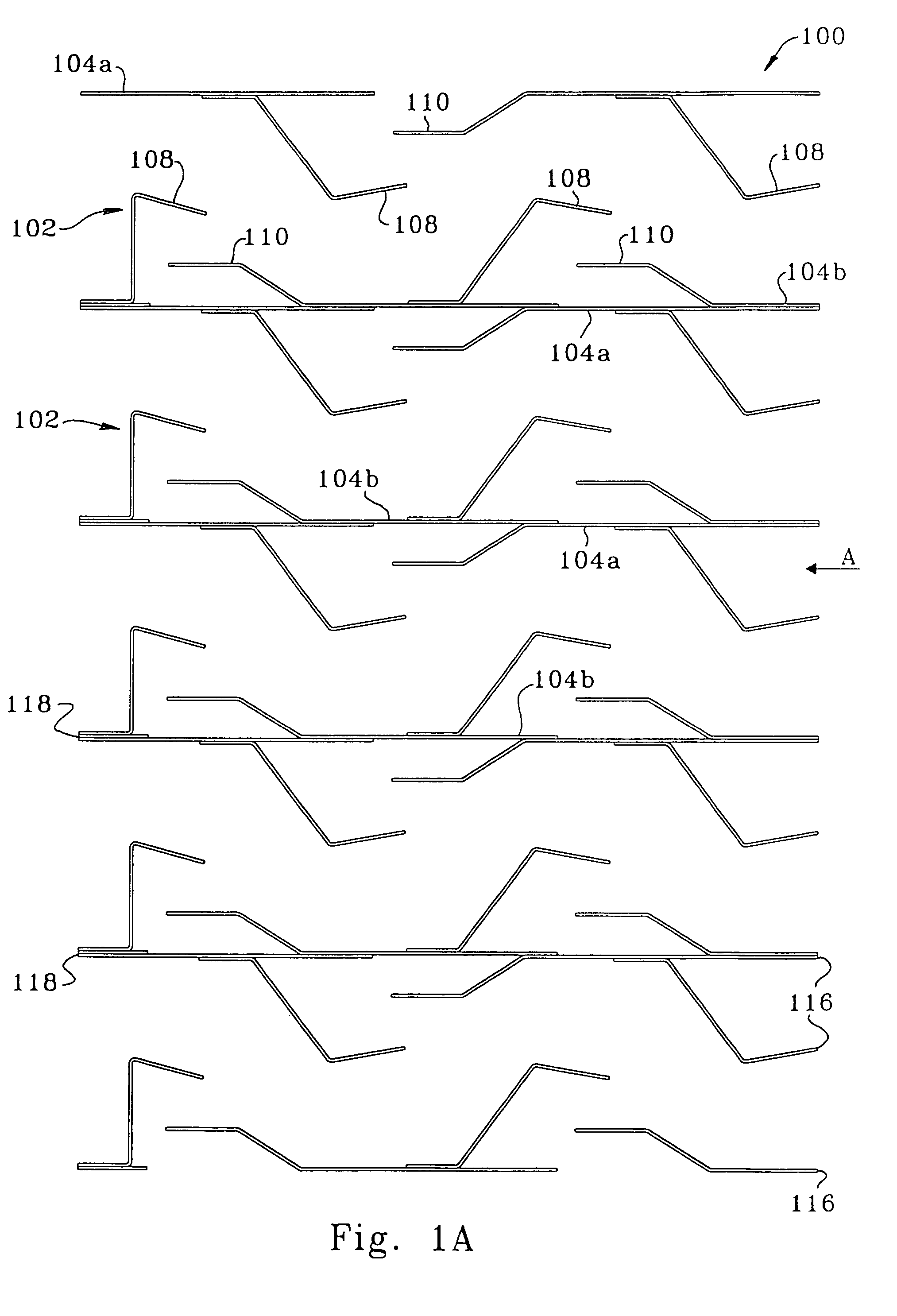
[0031]Referring to FIG. 1A, there is shown a top view of a central section illustrating the arrangement of vanes or sheets and integral louvers defining the fluid flow channels according to one embodiment of the present invention. The mist eliminator or demister 100 includes a plurality of corrugated sheets 102, a plurality of flat sheets 104a and 104b, and an outer frame shown in FIG. 1B. Each of the corrugated sheets 102 comprises a plurality of integral louvers 108 and the flat sheets 104a, 104b comprise integral louvers 110. The sheets or vanes have a leading edge 116 proximate the inlet of the vapor-liquid separator or demister and a trailing edge 118 proximate the vapor outlet.

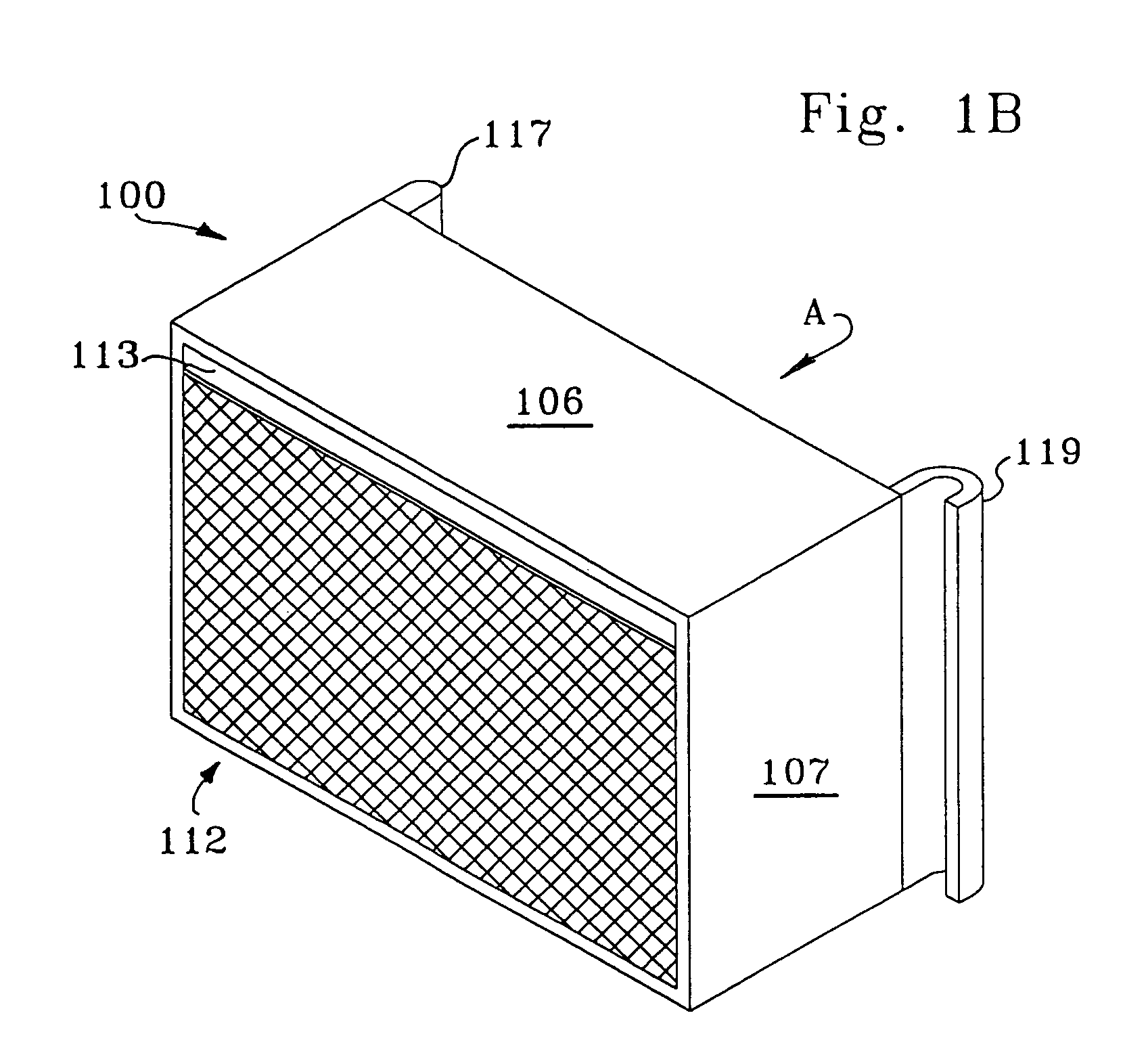
[0032]FIG. 1B shows one embodiment of an outer frame having a solid top plate 106 and two solid sidewalls 107 that are welded together or otherwise securely assembled to contain the corrugated sheets 102 and the flat sheets 104a, 104b. The outer frame in this embodiment includes perforated plates where v...


PUM

PropertyMeasurementUnit
densityaaaaaaaaaa
vapor-liquid separationaaaaaaaaaa
velocityaaaaaaaaaa

Abstract

The invention provides a vane-type mist eliminator device having formed or corrugated sheets, flat sheets, and integral louvers. The corrugated sheets and flat sheets are layered such that the arrangement of sheets and integral louvers creates at least one tortuous fluid flow channel from an inlet to a vapor outlet of the device An outer casing or frame is sufficient to hold the sheets together.

Description

FIELD OF THE INVENTION[0001]This invention relates to devices for separating a liquid and a vapor.BACKGROUND OF THE INVENTION[0002]Many industrial processes use vapor-liquid separation devices to remove liquid droplets from a vapor stream. For the purposes of this application, the terms “vapor” and “gas” are used interchangeably. In mass and / or heat transfer equipment, liquid droplets are often generated through vapor-liquid contacting or phase change. An example of one such process is co-current fractionation wherein a generally downward flowing liquid phase contacts an upward flowing vapor phase. Although the overall flow of vapor and liquid in this process is counter-current, the flow of vapor and liquid is co-current when the vapor and liquid are contacted as the liquid is entrained in the vapor and carried upward to a vapor-liquid separation device wherein the liquid is de-entrained from the vapor. The liquid then flows downward to an inferior stage and the vapor flows upward t...

Claims


Application Information

Patent Timeline
Patent Type & Authority Patents(United States)
IPC IPC(8): B01D45/00
CPCB01D45/08B01D45/00
Inventor AGNELLO, JOSEPHHELDWEIN, THOMAS C.XU, ZHANPINGMUCK, AARON J.
Owner UOP LLC
Why Eureka
Try Eureka