Optical selectable force impact tool

a force impact tool and selectable technology, applied in the field of electrical wiring, can solve the problems of inability to meet the requirements of electrical contact, inability to accurately set, and significant damage to the connector or the panel on which it is mounted, etc., and achieves the effect of quick and easy adjustment, correct setting, and convenient access and visibility

Inactive Publication Date: 2009-11-24
SULLSTAR TECH
View PDF5 Cites 12 Cited by
  • Summary
  • Abstract
  • Description
  • Claims
  • Application Information

AI Technical Summary

Benefits of technology

[0015]According to the present invention an impact tool for wire end termination is provided which is user-friendly, is quickly and easily adjustable to meet the optimal impact force level needed when moving from one job to another, and will achieve precisely correct insertion of the conductor wire without damage to either the wire or the connector panel. The pre-set compression of the main drive spring is adjusted by hand with an adjustment screw that is readily accessible and visible, and can be correctly set without the need for a separate screwdriver or other tool.

Problems solved by technology

If a conductor wire is not inserted far enough to reach the “sweet spot” the electrical contact may be inferior.
And if the conductor wire is pushed in too far, there may be significant damage to the connector or to the panel on which it is mounted.
During recent years, due largely to the deregulation of the industry, many manufacturers have made all of the relevant products—the connector circuit panels, the insulated conductors attached to the panels, and the tools for accomplishing the attachment—to differing and non-uniform technical standards.
Due to those differences in standards for the products of different companies the previously accepted industry-wide standards for wire insertion are no longer reliable.
If too low a spring compression level is used, the conductor wire may not become conductively seated to the full extent that is desired.
If too high a compression level is used, there is a danger that the delicate mechanism of the connection panel circuit board may be damaged.

Method used


Image

  • Optical selectable force impact tool
  • Optical selectable force impact tool
  • Optical selectable force impact tool

Examples


Embodiment Construction

FIGS. 1-5

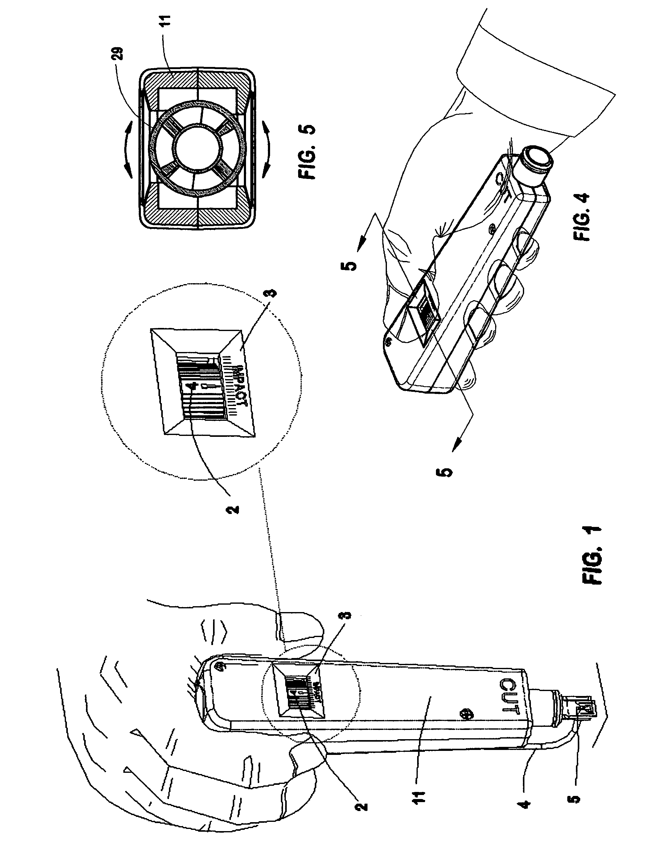
[0021]As shown in FIG. 1 of the drawings, the hand-held tool assembly has an elongated hollow housing 11 the upper end of which is shaped to be grasped by hand. A wire end termination tool 5 attached to lower end of the assembly receives a conductor wire 4 that is to be inserted into an insulation-displacement connector.

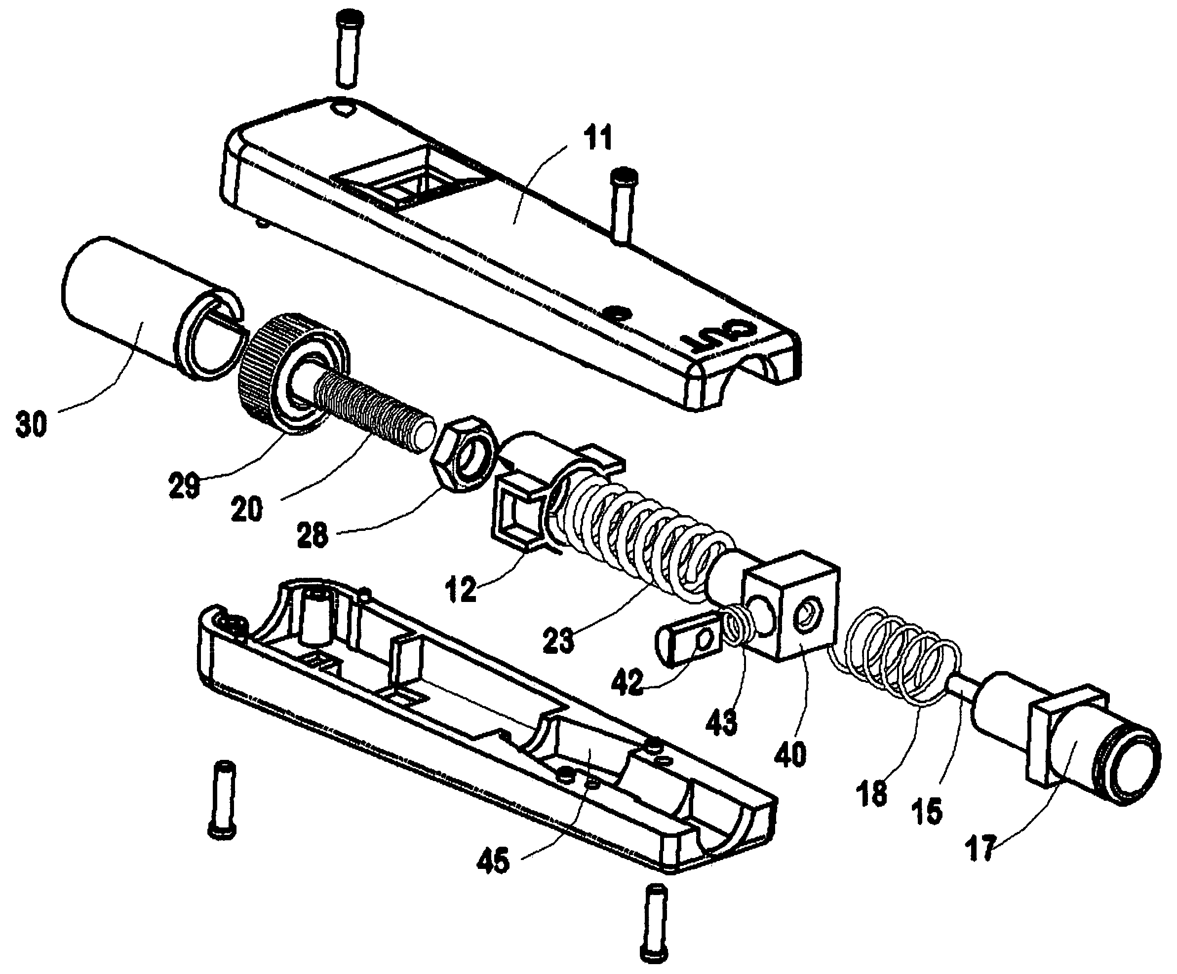
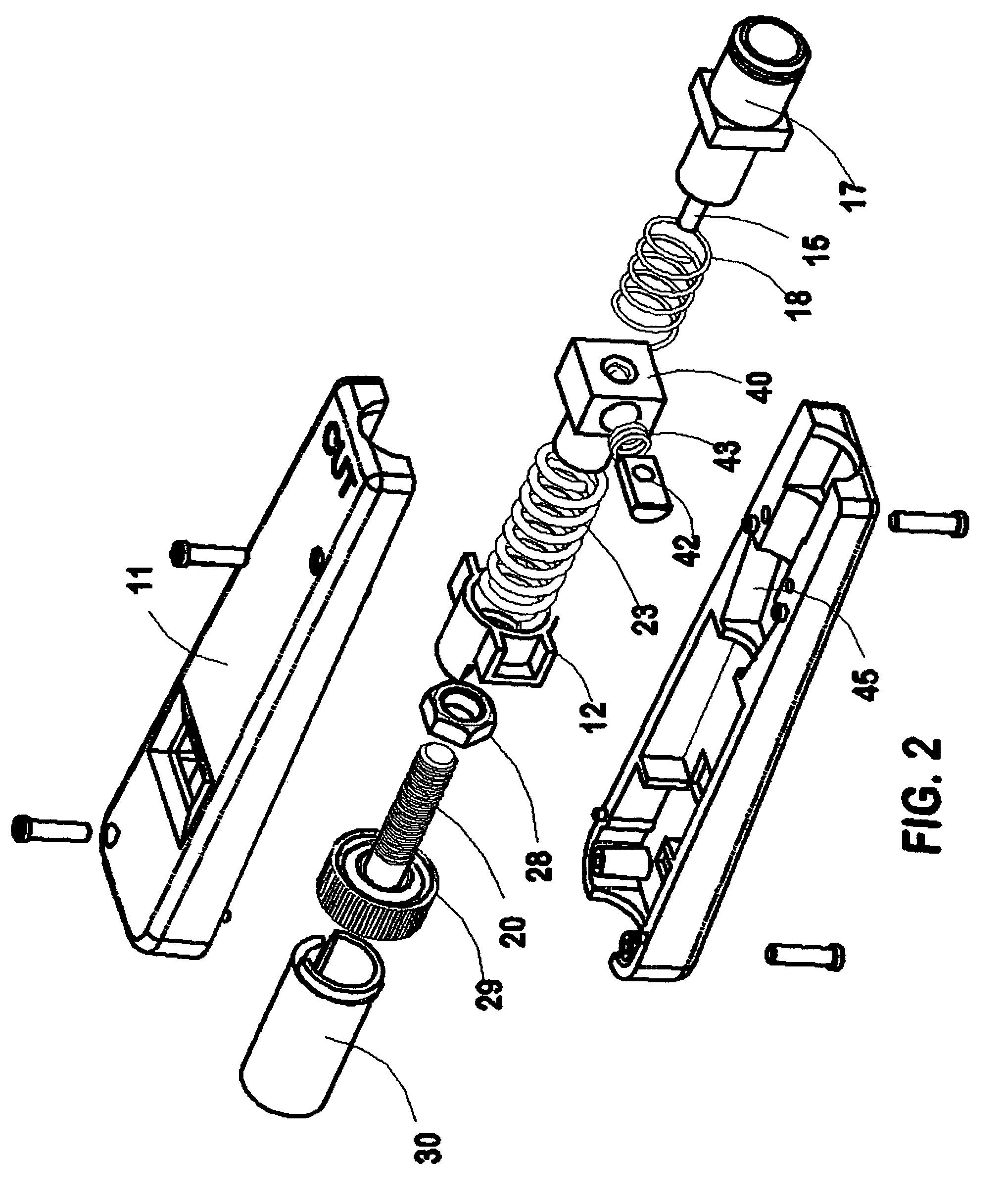
[0022]Reference is now made particularly to FIG. 2. The housing 11 is made of two plastic parts which fit together to contain all parts of the mechanism. An adjustment screw 20 has a knurled knob 29 on its upper end. The screw 20 is held in a centered rotatable position by the adjustment screw support member 30, and adapter 12, held fast by the housing. The threaded shank of screw 20 engages a nut 28, which acts as a drive spring seat, held in a non-rotatable relation to the housing by the drive spring adapter 12. Adapter 12 is itself non-rotatable in the housing and has in its upper end a hexagonal opening, not specifically shown in the drawing, which recei...


PUM

PropertyMeasurementUnit
impact forceaaaaaaaaaa
forceaaaaaaaaaa
distanceaaaaaaaaaa

Abstract

An user-friendly impact tool for wire end termination in which the pre-set compression of a main drive spring is adjusted by hand with an adjustment screw having a knurled knob that is both visible and hand-accessible through an opening in the housing wall, and also having a vernier scale formed partly on the outer housing wall surface and partly on the knurled knob itself to correctly indicate the pre-load adjustment position of the drive spring.

Description

CROSS-REFERENCE TO RELATED APPLICATION[0001]This application claims the priority of my prior copending application Ser. No. 11 / 129,257 filed May 13, 2005 which is entitled STEADY-FORCE METHOD AND APPARATUS FOR WIRE END TERMINATION AND CUTTING.FIELD OF THE INVENTION[0002]This invention relates to making electrical wiring connections in telecommunication connector blocks or terminals.DESCRIPTION OF RELATED PRIOR ART[0003]U.S. Pat. No. 3,708,852 issued in 1973 to Mason shows a hand-operated impact tool for creating an impact from a hammer onto a wire termination tool for shock loading the tool blade onto a wire that is to be inserted into a connector. The impact was created by compressing a hammer spring 80—otherwise known as a main drive spring—and then suddenly releasing the main drive spring by a mechanical trigger so that its accumulated compression would drive the hammer 76 downward. Thus the main spring that was manually compressed to a predetermined level could be abruptly relea...

Claims


Application Information

Patent Timeline
Patent Type & Authority Patents(United States)
IPC IPC(8): H01R43/00
CPCH01R43/015Y10T29/53217Y10T29/5151Y10T29/53222Y10T29/53226
Inventor SULLIVAN, ROBERT W.
Owner SULLSTAR TECH
Why Eureka
Try Eureka