Heat sink with heat pipes and method for manufacturing the same

a heat sink and heat pipe technology, applied in the field of heat sinks, can solve the problems of reduced design flexibility, insufficient heat spreading effect, and inability to form holes or grooves in the base plate, so as to reduce the weight of the base portion, and reduce the weight of the entire heat sink

Active Publication Date: 2009-11-24
FURUKAWA ELECTRIC CO LTD
View PDF31 Cites 18 Cited by
  • Summary
  • Abstract
  • Description
  • Claims
  • Application Information

AI Technical Summary

Benefits of technology

[0008]The inventors have made various investigations and experiments with respect to the disadvantages of the conventional heat sinks and found the following facts. That is, if a heat pipe is placed between a first plate member and a second plate, a machine work, such as cutting, for mounting heat pipes becomes unnecessary and the fabricating cost is reduced. In addition, since a space is formed around the heat pipe, the weight of the base portion is reduced and therefore a reduction in the weight of the entire heat sink is achieved. Furthermore, since a portion of the base portion near a heat source has an area that can exchange heat with the surrounding air, it has been found that an enhancement in the heat dissipating ability and an increase in the amount of the surrounding air due to a reduction in passage resistance can be expected.

Problems solved by technology

Copper is excellent in thermal conductivity, but when the base plate of a heat sink is large or when a heat source is arranged close to an end portion of the base plate, the effect of spreading heat is not sufficient.
However, vapor chambers are costly and holes and screw holes for mounting them have to be designed from the beginning, so that design flexibility is reduced.
On the other hand, when installing heat pipes, holes or grooves must be formed in the base plate.
In addition, when the heat spreader is installed, the thickness of the base plate is increased, thus the material cost is increased and the increased weight requires a redesign for the fixing method thereof, or the like.

Method used


Image

  • Heat sink with heat pipes and method for manufacturing the same
  • Heat sink with heat pipes and method for manufacturing the same
  • Heat sink with heat pipes and method for manufacturing the same

Examples


embodiment 1

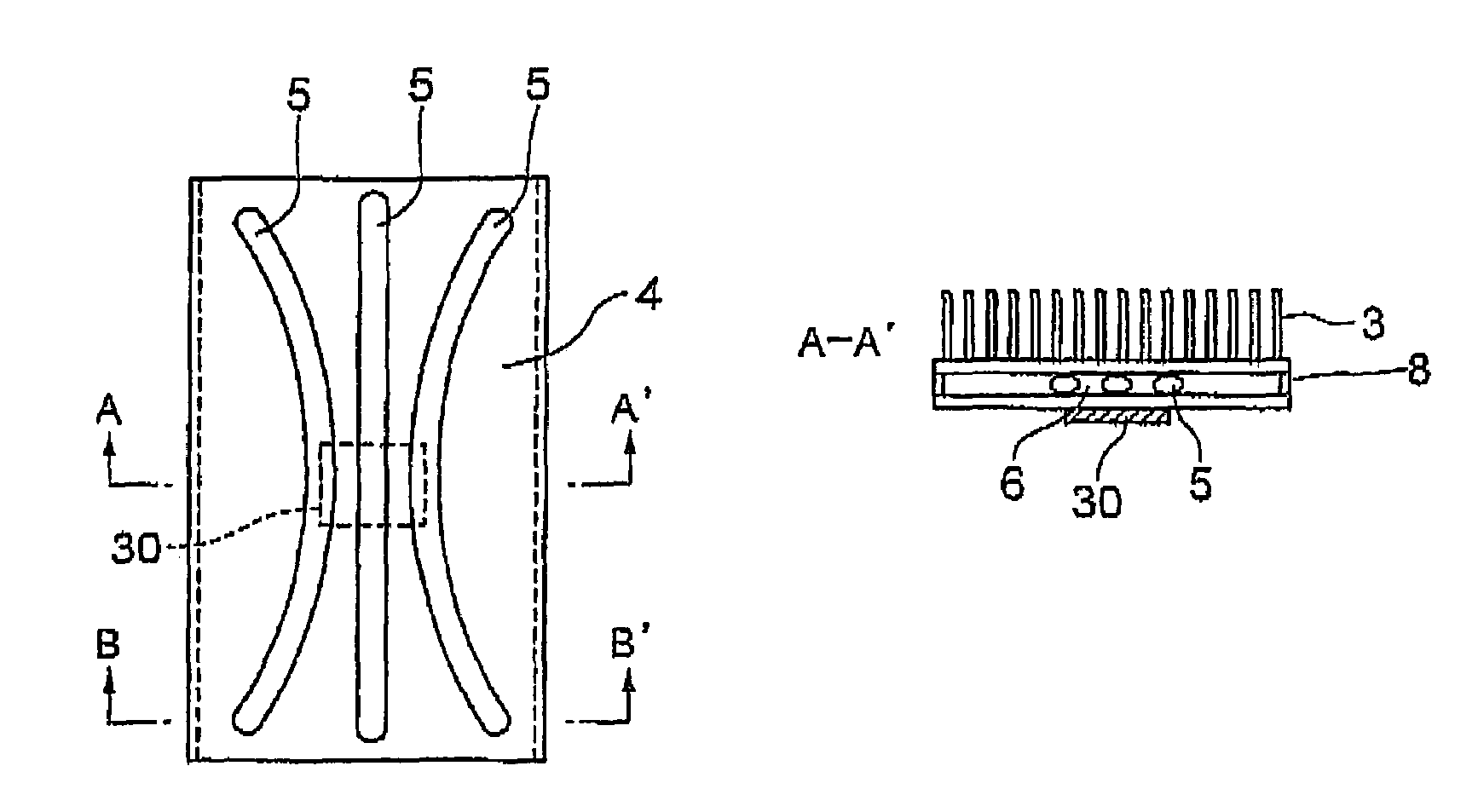
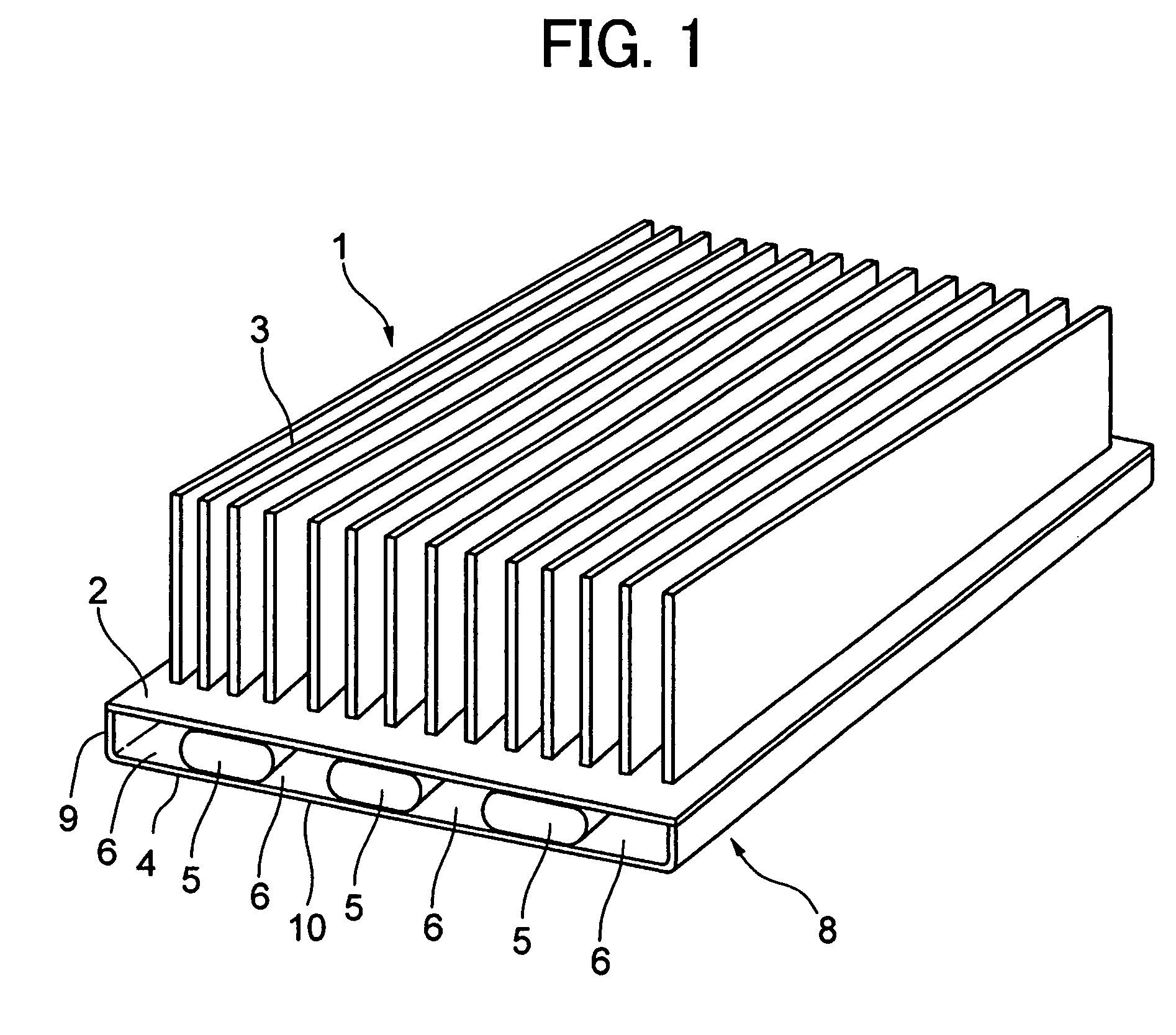
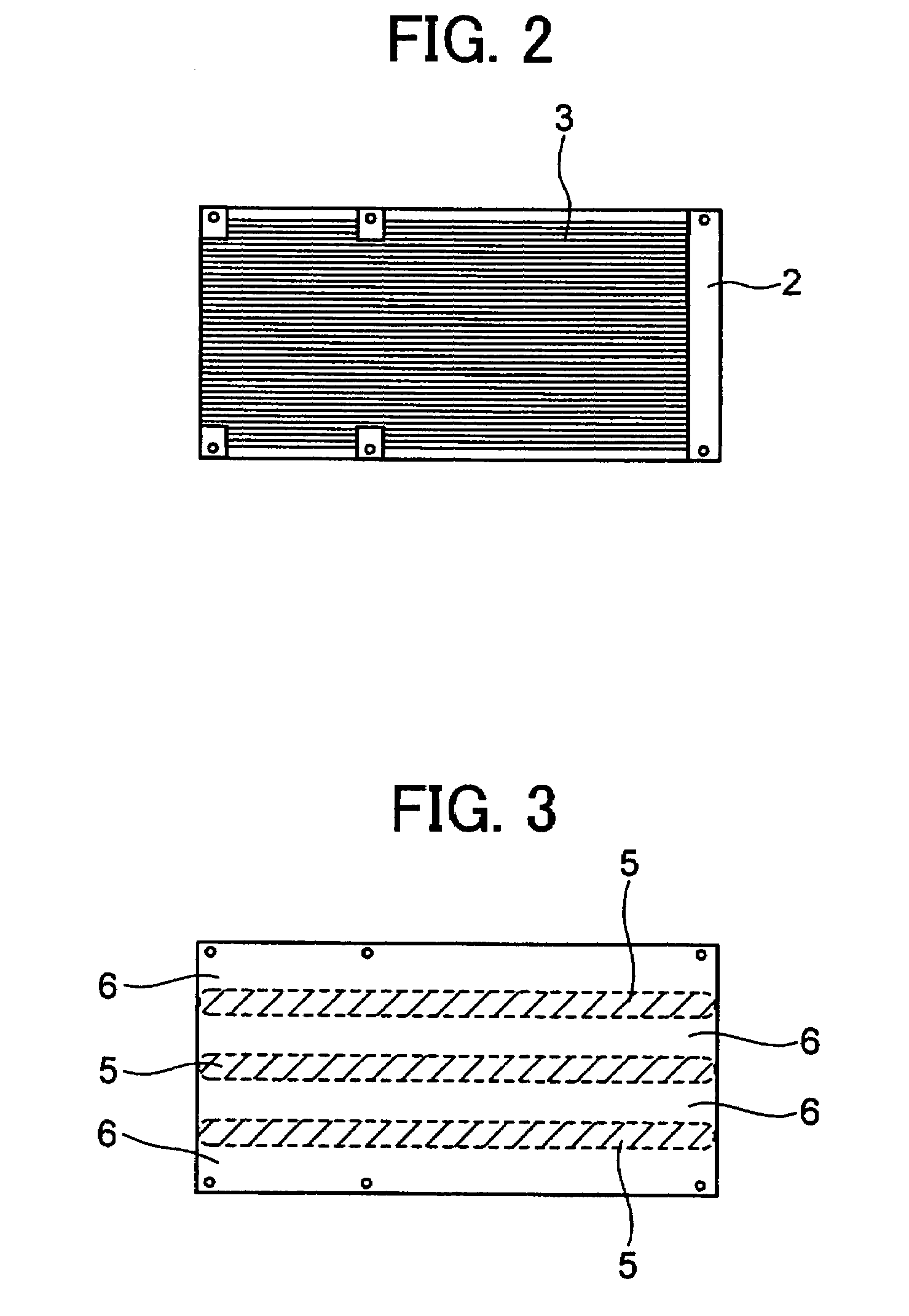
[0099]The heat sink 1 with heat pipes 5 of the present invention shown in FIG. 1 was made. In this embodiment, a copper plate of 1.2 mm in thickness was used in the first plate member 4 and a copper plate of 0.8 mm in thickness was used in the second plate member 2. Three flattened heat pipes which are transformed from 6 mm in diameter to 3 mm in thickness were arranged between the first and second plate members. The height was 20 mm in total. The three heat pipes were arranged at equal spaces within the base portion 8. The fin thickness was 0.3 mm.

[0100]A heat source is arranged at the center of the short edge of the first plate member and at a position 20 mm away from one end of the long edge. Although one of the three heat pipes was positioned just above the heat source, heat was also distributed to the remaining two heat pipes. Therefore, an increase in the amount of input heat and the heat density, which can cause the dry-out of the heat pipes, could be reduced. In addition, si...

embodiment 2

[0101]The heat sink 10 with heat pipes 15 of the present invention shown in FIG. 5 was made. The construction is nearly the same as the embodiment 1, but the metal block 17 is provided between the first plate member 14 and the second plate member 12. The metal block (or center block) 17 of 10 mm in width is provided at the center portion of the short edge of the first plate member 14 and extends from one end of the long edge to the other end. On both sides of the center block, there are provided two heat pipes. The heat pipe is approximately 15 mm in width.

[0102]The position of a heat source is the same as the embodiment 1. In this case, the center block is positioned just above the heat source, and the thermal diffusion effect is further obtained in addition to the thermal diffusion effect of the first plate member of 1.2 mm in thickness. As a result, heat flux is reduced when heat is transferred to the heat pipe, so even when calorific value of the heat source is greater than that...


PUM


Abstract

A heat sink to be used with a heat source can include a base portion and a fin portion. The base portion can include a plurality of heat pipes and a space formed at least partially between adjacent heat pipes. The base portion can also include a first plate thermally connected to the heat source and a second plate thermally connected to the fin portion. The plurality of heat pipes contacts the first plate and the second plate. The plurality of heat pipes can also include a first portion that is closer than a second portion to the heat source. Additionally, a distance between adjacent heat pipes is smaller at the first portion than at the second portion.

Description

CROSS-REFERENCE TO RELATED APPLICATIONS[0001]This application is a continuation application of the U.S. patent application Ser. No. 10 / 936,850 filed Sep. 9, 2004, the contents of which are incorporated by reference herein in their entirety, priority to which is claimed under 35 U.S.C. § 120; U.S. patent application Ser. No. 10 / 936,850 claims the benefit of the date of the earlier filed provisional application, U.S. Provisional Application No. 60 / 502,821, filed on Sep. 12, 2003, the contents of which are incorporated by reference herein in its entirety.FIELD OF THE INVENTION[0002]The present invention relates to a heat sink in which heat pipes and a space (which functions as an air passages) are provided inside of a base portion having a fin portion mounted thereon, and a method for manufacturing the heat sink.DESCRIPTION OF THE RELATED ART[0003]A method of mounting fins on a base plate (which is a heat-receiving portion) to dissipate the heat of a heat-generating member is in genera...

Claims


Application Information

Patent Timeline
Patent Type & Authority Patents(United States)
IPC IPC(8): F28D15/00H05K7/20F28D15/02H01L23/427
CPCF28D15/0233F28F3/02F28D15/0275
Inventor KAWABATA, KENYAOOMI, MASARUOHNO, RYOJI
Owner FURUKAWA ELECTRIC CO LTD
Why Eureka
Try Eureka