Plastic headrest frame

a headrest frame and plastic technology, applied in the field of headrests for automobiles, can solve the problems of lack of rigidity of the headrest frame compared with the one made of formed plastic, and the inability to effectively protect the person in the car, so as to reduce the impact

Inactive Publication Date: 2009-11-24
FUKUDA TOYOSHI
View PDF7 Cites 13 Cited by
  • Summary
  • Abstract
  • Description
  • Claims
  • Application Information

AI Technical Summary

Benefits of technology

[0006]A headrest frame made of formed plastic lacks rigidity when compared with a headrest frame made of iron. Therefore, there is a concern for its inability to effectively protect the person in the car at the time of an accident, because the impact of the accident might break the headrest frame, and the headrest frame becomes unable to support the headrest properly. Thus, the invention provides an automotive headrest frame that can reduce the impact that might be applied to the person in the car at the time of an accident by devising a new shape in the cross-section of embedded core material to realize plastic rigidity that is equal to that of the iron headrest frame.

Problems solved by technology

A headrest frame made of formed plastic lacks rigidity when compared with a headrest frame made of iron.
Therefore, there is a concern for its inability to effectively protect the person in the car at the time of an accident, because the impact of the accident might break the headrest frame, and the headrest frame becomes unable to support the headrest properly.

Method used


Image

  • Plastic headrest frame
  • Plastic headrest frame
  • Plastic headrest frame

Examples


first embodiment

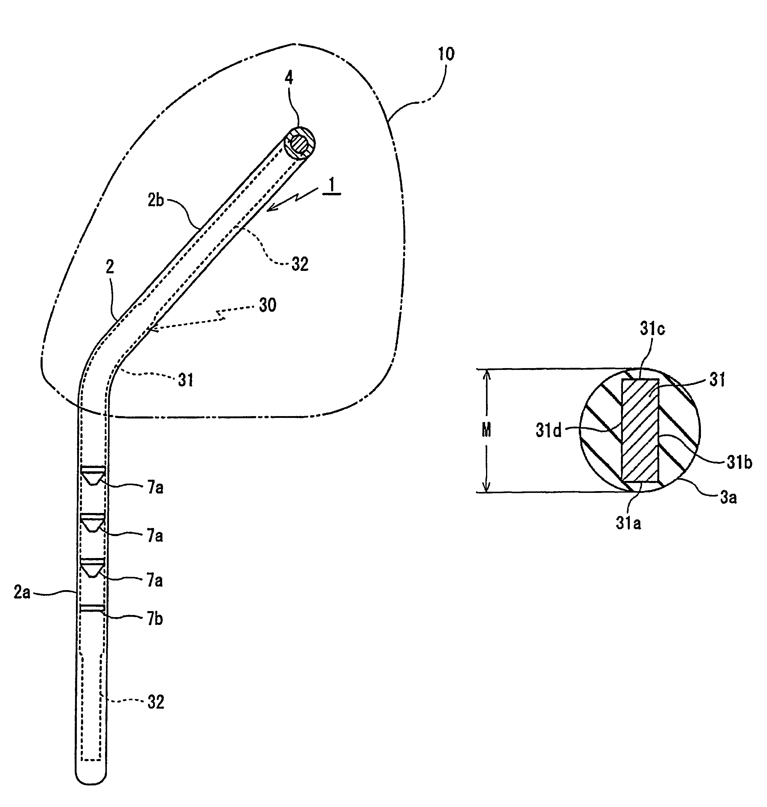
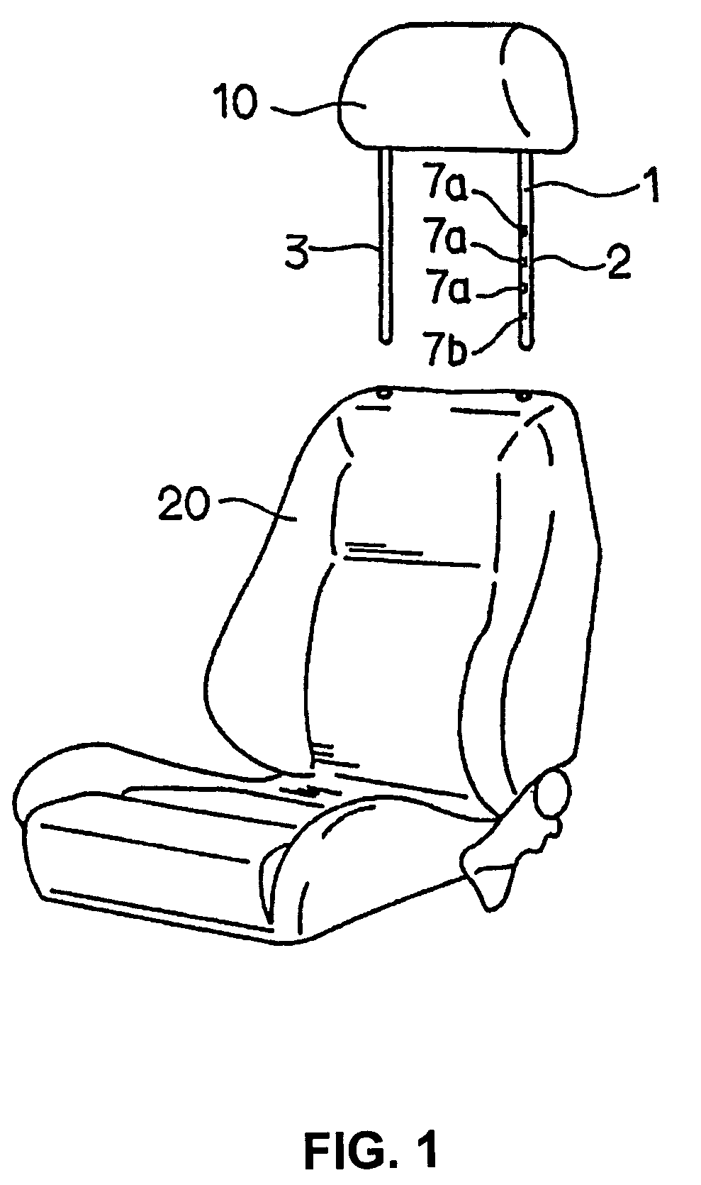
[0025]FIG. 1 shows a headrest frame 1 according to the invention. A headrest 10 is disposed on the headrest frame 1, and the headrest frame 1 is adapted to be installed on a car seat 20 to support the headrest 10 with respect to the car seat 20. Together, the car seat 20, the headrest frame 1, and the headrest 10 define a seating assembly for use in an automobile (not shown) having a front end toward the normal direction of travel, a rear end opposite the normal direction of travel, and opposed sides, wherein the seating assembly faces the front end of the automobile. The headrest frame 1 has a first leg 2 and a second leg 3 that are receivable within the car seat 20 for connecting the headrest frame 1 to the car seat 20. A plurality of recesses 7a, 7b are formed on the headrest frame 1 for adjustably connecting the headrest frame 1 to the car seat 20, as will be described in detail herein.

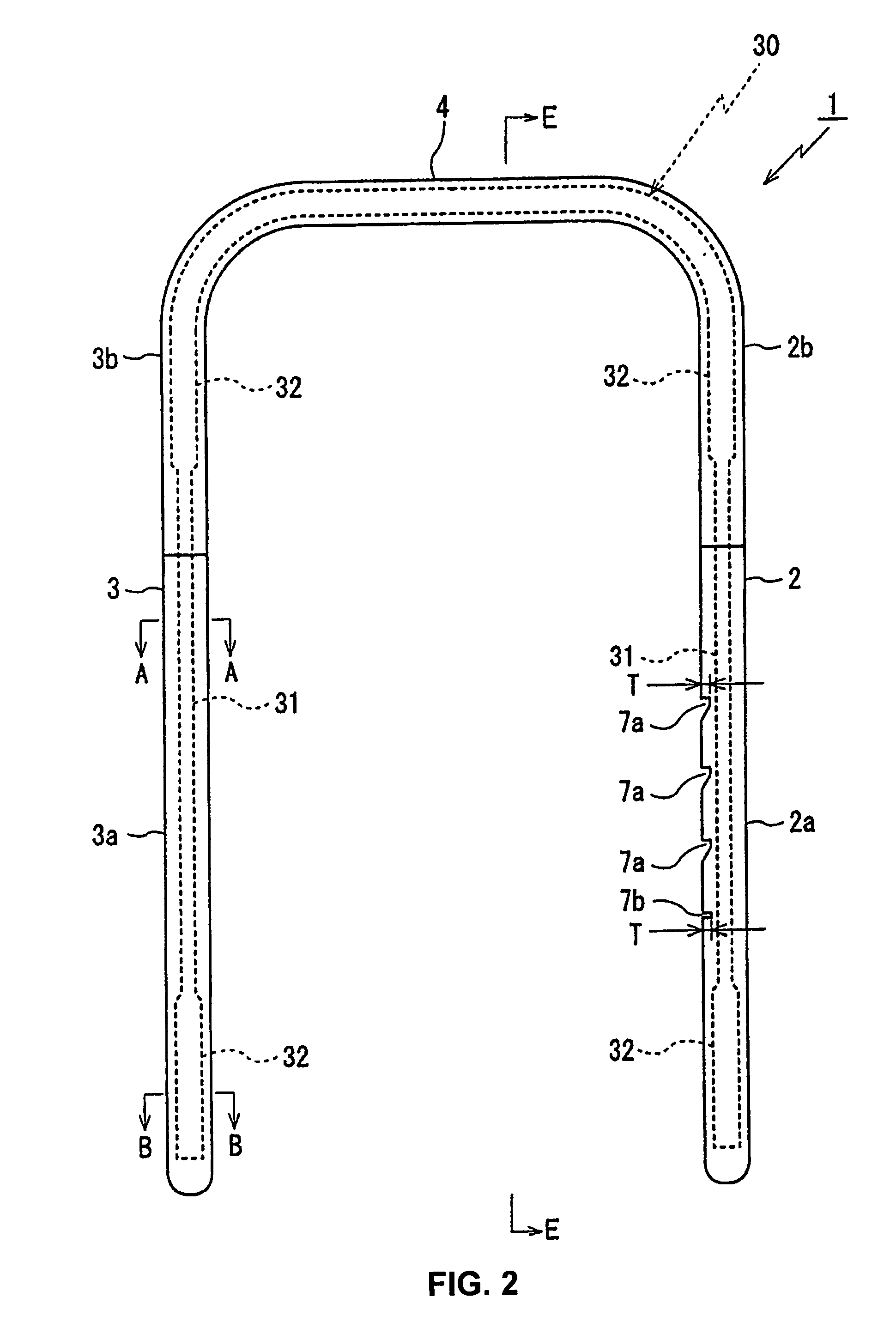
[0026]As best seen in FIG. 2, the first leg 2 and the second leg 3 of the headrest frame 1 are...

second embodiment

[0042]As a further alternative in either the first or second embodiment, rigidity of the headrest frame may be improved by providing a horizontal bar 5. The horizontal bar 5 interconnects the legs 2, 3 near the intersection of the vertical lower portions 2a, 3a and the slanting portions 2b, 3b of the legs 2, 3.

[0043]From the foregoing embodiments, it will be appreciated that by providing the headrest frame 1 of the invention with the one-piece core material 30 embedded throughout the two legs 2, 3 and the connecting bar 4, and by providing at least a portion of the core material 30 with a rectangular cross-section portion 31 in each of the legs 2, 3, wherein the rectangular cross-section portion 31 is aligned with the narrow sides 31a, 31c thereof aligned to face the front and the back of the car when installed on the car seat 20, the rigidity of the headrest frame 1 can be sufficiently increased against the stress applied to the headrest frame 1 during a crash. Therefore, even thou...


PUM

PropertyMeasurementUnit
widthaaaaaaaaaa
widthaaaaaaaaaa
widthaaaaaaaaaa

Abstract

A headrest frame fabricated from a plastic material and having a core material with a cross-sectional shape that provides rigidity equal to that of a headrest frame fabricated from iron. The headrest frame has at least a first elongate leg having a core material embedded within a first plastic material. The first plastic material has a substantially round cross-sectional shape in the first elongate leg. At least a portion of the core material in said first elongate leg has a substantially rectangular cross-sectional shape.

Description

CROSS-REFERENCE TO RELATED APPLICATIONS[0001]This application claims the benefit of Japanese Patent Application No. 2006-274167, filed Oct. 5, 2006.FIELD OF THE INVENTION[0002]The invention relates to the field of headrests for automobiles, and more particularly, the invention relates to a plastic headrest frame that supports a headrest with respect to a seat in an automobile.BACKGROUND OF THE INVENTION[0003]It is well known to support a headrest with respect to a seat in an automobile by using a frame, and such headrest frames typically provide for adjustment of the headrest with respect to the seat of the automobile. During an automotive collision, the headrest functions to stabilize the head of a vehicle occupant who is seated in the seat. Of course, if the headrest frame were to break during the automotive collision, the headrest would no longer be operative to stabilize the head of the vehicle occupant, and the protections intended to be provided to the vehicle occupant by the ...

Claims


Application Information

Patent Timeline
Patent Type & Authority Patents(United States)
IPC IPC(8): A47C7/38B60N2/90
CPCB29C45/14549B29C45/1418B29K2705/00B29C45/14819A47C7/38
Inventor ODA, SHIGEO
Owner FUKUDA TOYOSHI
Why Eureka
Try Eureka