Method and apparatus for AC integrated current sensor

a current sensor and ac inductor technology, applied in the field of electric power systems, can solve the problems of reducing reliability, reducing reliability, adding extra weight, volume, cost and complexity to the electrical circuit, and heavy/high-cost of typical/conventional stand-alone current sensors and inductors

Inactive Publication Date: 2009-11-24
HONEYWELL INT INC
View PDF44 Cites 21 Cited by
  • Summary
  • Abstract
  • Description
  • Claims
  • Application Information

AI Technical Summary

Benefits of technology

[0009]The present invention is directed to integrated current sensors for use in AC electric power systems. According to a first aspect of the present invention, an integrated current sensor for use in an AC electric power system comprises: an inductor, wherein an AC current passes through the inductor; an integrator circuit, the integrator circuit receiving a voltage associated with the AC current; a gain control circuit operationally connected to the integrator circuit, the gain control circuit outputting a gain controlled signal; and a compensation circuit operationally connected to at least two of the integrator circuit, the gain control circuit, and the inductor, to compensate for parameter variation induced in the gain controlled signal or in the output of the integrator circuit.

Problems solved by technology

Typical / conventional stand-alone current sensors and inductors are heavy and expensive, and need to be used together with bus-bars, cables, and other mounting fixtures inside a circuit.
Hence, installation of typical / conventional current sensors in electric power systems causes significant disturbances.
Hence, additional parts are needed with typical / conventional current sensors, which reduces reliability and adds extra weight, volume, cost and complexity to electrical circuits.

Method used


Image

  • Method and apparatus for AC integrated current sensor
  • Method and apparatus for AC integrated current sensor
  • Method and apparatus for AC integrated current sensor

Examples


second embodiment

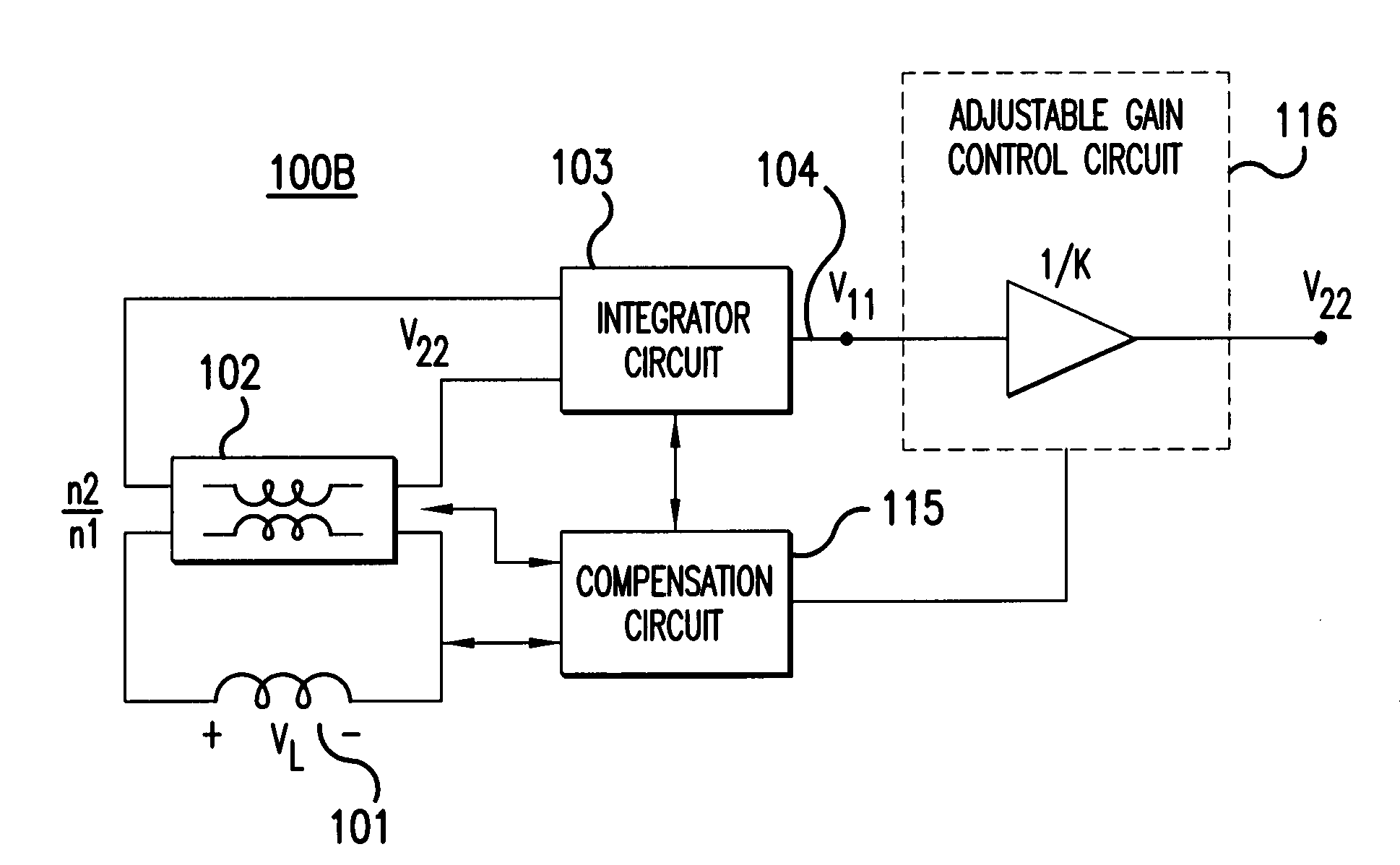
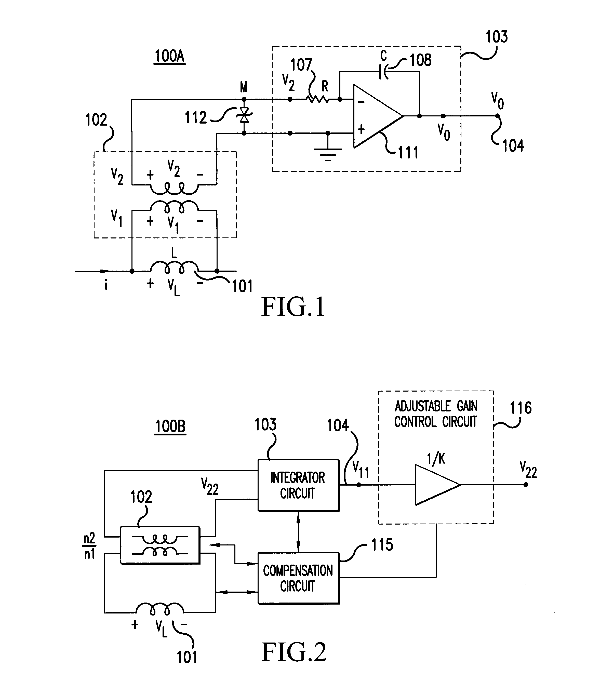
[0046]FIG. 2 illustrates a circuit diagram for an integrated current sensor 100B for AC circuits that controls gain and compensates for parameter variation according to the present invention. The integrated current sensor 100B illustrated in FIG. 2 includes the following components: an inductor 101; a transformer 102; an integrator circuit 103; an adjustable gain control circuit 116; and a compensation circuit 115. The adjustable gain control circuit 116 and the compensation circuit 115 are used to compensate for parameter variation and obtain a precision current sensor.

[0047]With the integrated current sensor 100B illustrated in FIG. 2, the current-to-voltage ratio can be maintained equal to unity, by monitoring the temperature, or other sources of circuit parameter variation, through the monitoring / compensation circuit 115. The gain for the integrated current sensor 100B is adjusted accordingly through adjustable gain control circuit 116.

[0048]In an alternative implementation, the...

third embodiment

[0054]FIG. 5A illustrates design aspects for an integrated current sensor that includes the effect of inductor resistance according to the present invention.

[0055]For the circuit illustrated in FIG. 1, inductor resistance RL was assumed to be much smaller than ω0L, where ω0 is the fundamental frequency associated with current and voltage waveforms that pass through the inductor 101. FIG. 5A presents a more detailed analysis of inductor performance including inductor resistance RL.

[0056]As illustrated in FIG. 5A, an inductor component 201 having an inductor resistance can be represented by a circuit that includes an inductor 203 of inductance L and a resistor 206 of resistance RL. In equations (1) and (2) associated with FIG. 1, the effect of inductor resistance was ignored, as is appropriate for the case when ω0L>>RL, where ω0 represents the fundamental frequency component through the inductor component 201.

[0057]For an inductor component 201 having an inductance L and a resistance ...

fourth embodiment

[0069]FIG. 6A illustrates an integrated inductor / AC current sensor 100D using a second inductor winding according to the present invention. The integrated inductor / AC current sensor 100D illustrated in FIG. 6A includes the following components: a first winding 409 with n1 turns; a second winding 411 with n2 turns; a core 403; cooling brackets 407 with cooling bracket surfaces 401; a burden resistor 417 of resistance R0; and a twisted pair 415 for signal transmission. The core 403 includes an airgap 413. The second winding 411 for the inductor is introduced to measure AC current in the same manner as a current transformer. This winding arrangement is advantageous because the inductor and the current transformer share the core and the primary winding. Hence, only one simplified installation and one thermal management system are required for the integrated inductor / current sensor 100D.

[0070]In FIG. 6A, AC inductor current iL passes through the first winding 409 with n1 turns. Cooling b...


PUM


Abstract

Integrated current sensors are used in AC electric power systems. An integrated current sensor according to one embodiment comprises: an inductor (101), wherein an AC current passes through the inductor (101); an integrator circuit (103), the integrator circuit (103) receiving a voltage associated with the AC current; a gain control circuit (116) operationally connected to the integrator circuit (103), the gain control circuit (116) outputting a gain controlled signal; and a compensation circuit (115) operationally connected to at least two of the integrator circuit (103), the gain control circuit (116), and the inductor (101), to compensate for parameter variation induced in the gain controlled signal or in the output of the integrator circuit (103).

Description

[0001]The present application claims priority under 35 USC §119(e) to U.S. Provisional Application No. 60 / 849,837 filed Oct. 6, 2006, which is hereby incorporated by reference herein in its entirety.CROSS REFERENCE TO RELATED APPLICATIONS[0002]This non-provisional application is related to co-pending non-provisional application titled “Method and Apparatus for DC Integrated Current Sensor” filed concurrently herewith, the entire contents of which are hereby incorporated by reference.BACKGROUND OF THE INVENTION[0003]1. Field of the Invention[0004]The present invention is related to electric power systems, and more particularly to a method and apparatus for integrating an AC current sensor with an AC inductor.[0005]2. Description of the Related Art[0006]Current sensors are essential components in electric power systems. Current sensors determine current magnitude and direction at various circuit locations, facilitate proper control, protection and / or monitoring of the overall electric...

Claims


Application Information

Patent Timeline
Patent Type & Authority Patents(United States)
IPC IPC(8): G01R15/18
CPCG01R19/0015G01R1/203G01R31/008G01R15/183
Inventor KOJORI, HASSAN ALI
Owner HONEYWELL INT INC
Why Eureka
Try Eureka