Method for enabling monitoring of power consumption

Active Publication Date: 2009-11-24
SUNPOWER CORPORATION
View PDF7 Cites 45 Cited by
  • Summary
  • Abstract
  • Description
  • Claims
  • Application Information

AI Technical Summary

Benefits of technology

[0005]A method for enabling monitoring of power consumption at a site, the site comprising an electrical load connected to a power source through a junction, the power source connected to the junction by an electrical conductor and a fuel-less energy producing device electrically connected to the junction, is carried out as follows. A current sensor is electromagnetically coupled to the electrical conductor at a sensing position between the power source and the junction without direct electrical connection to the electrical conductor to create a current sensor signal. A sensed current signal and a sensed voltage signal are produced

Problems solved by technology

However, the corresponding information is typically not read

Method used


Image

  • Method for enabling monitoring of power consumption
  • Method for enabling monitoring of power consumption
  • Method for enabling monitoring of power consumption

Examples


Embodiment Construction

[0016]The following description will typically be with reference to specific structural embodiments and methods. It is to be understood that there is no intention to limit the invention to the specifically disclosed embodiments and methods but that the invention may be practiced using other features, elements, methods and embodiments. Preferred embodiments are described to illustrate the present invention, not to limit its scope, which is defined by the claims. Those of ordinary skill in the art will recognize a variety of equivalent variations on the description that follows. Like elements in various embodiments are commonly referred to with like reference numerals.

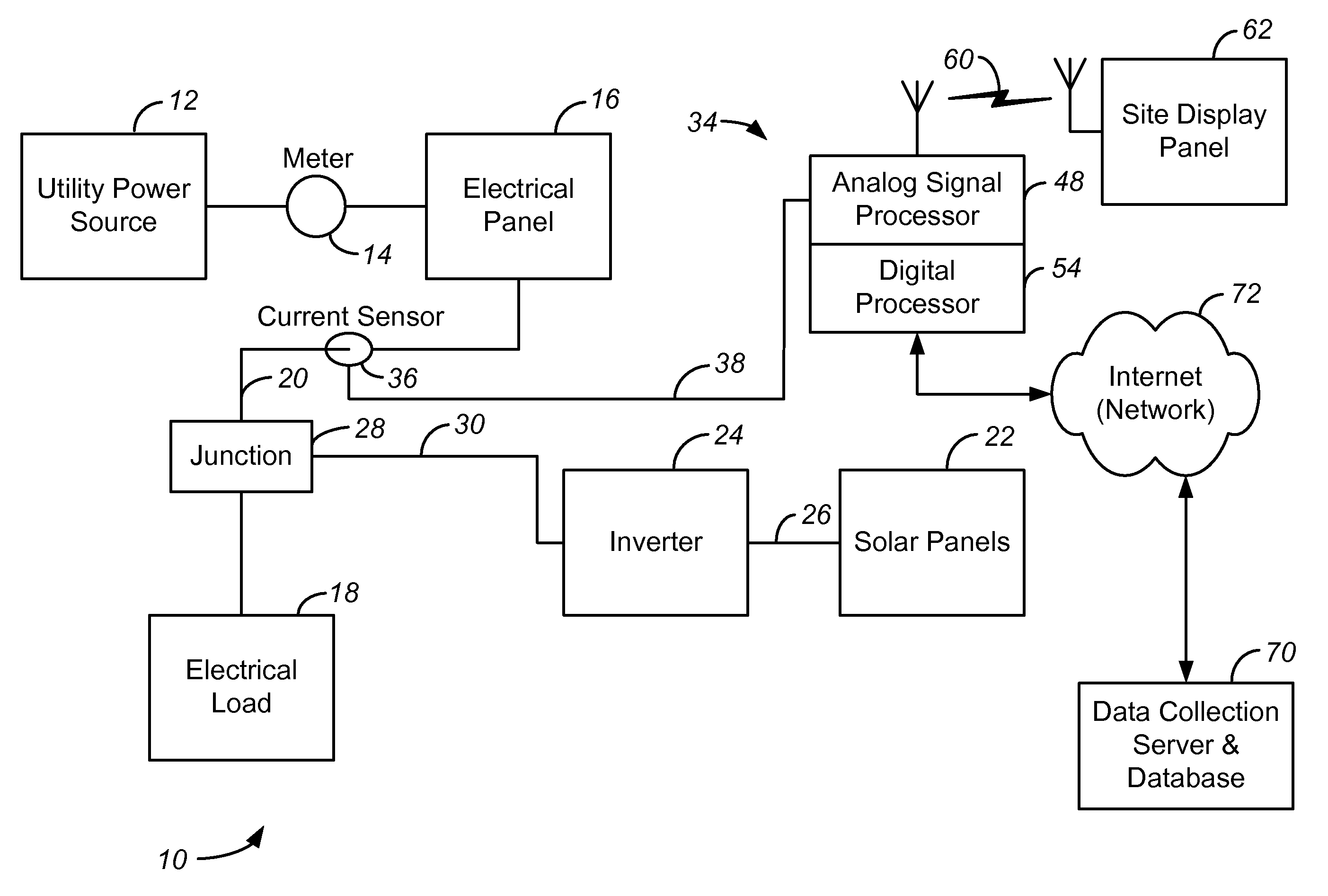
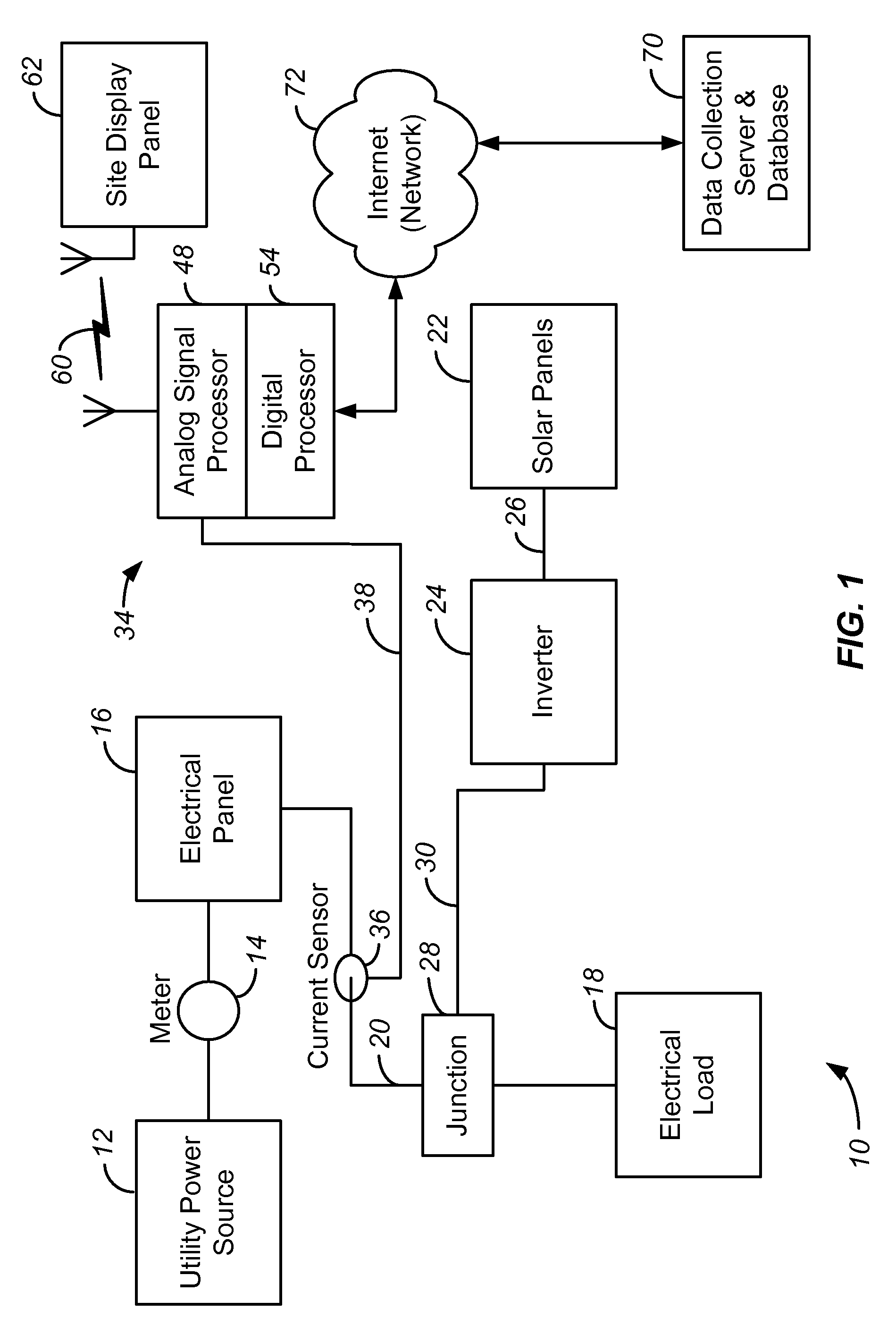
[0017]The invention is described with reference to solar panel installations. However, the invention can also be used with other types of fuel-less energy producing devices, such as wind powered energy machines and water powered energy machines.

[0018]One aspect of the invention is the recognition that it would be put ext...


PUM


Abstract

Power consumption at a site is monitored. An electrical load is connected to a power source by an electrical conductor. A fuel-less energy producing device is electrically connected to a junction along the electrical conductor. A current sensor is electromagnetically coupled to the electrical conductor at a sensing position between the power source and the junction to create a current sensor signal. Sensed current and voltage signals are produced from the current sensor signal. A sensed phase relationship between the sensed signals is determined and compared to a baseline phase relationship to determine the direction of current flow through the conductor. A power source signal, based on the current flowing through the conductor at the sensing position, is created. With some examples a Rogowski type differential current sensor is used. In some examples a single current sensor is used.

Description

FEDERALLY SPONSORED RESEARCH OR DEVELOPMENT[0001]This invention was made with Government support under DE-FC36-07GO17043 awarded by DOE. The Government has certain rights in this invention.CROSS REFERENCE TO OTHER APPLICATIONS[0002]This application is related to U.S. patent application Ser. No. 11 / 699,934, filed 30 Jan. 2008, entitled Method and Apparatus for Monitoring Energy Consumption of a Customer Structure.BACKGROUND OF THE INVENTION[0003]This invention relates to monitoring of energy use at a site, such as a home or a commercial building, which obtains power from both (1) a solar, wind or other fuel-less power source, and (2) another power source, typically a utility power source.[0004]It is useful to have information on current electrical energy consumption in a building, be it commercial or residential, obtaining energy from a fuel-less power source, typically solar panels. The information about the electrical energy produced by solar panels is commonly readily available th...

Claims


Application Information

Patent Timeline
IPC IPC(8): G01R31/28
CPCG01R21/133G01R21/06G01R19/165G01R22/06
Inventor ADAMS, FRANK J.KLEIN, DAVID L.
Owner SUNPOWER CORPORATION
Why Eureka
Try Eureka