
Top roller carrier for drafting systems in spinning machines

a top roller and drafting technology, which is applied in the direction of drafting machines, textiles and papermaking, yarn, etc., can solve the problems of disadvantageously affecting the adjustment of field width, and achieve the effect of simple flexible top aprons, excellent apron synchronisation, and easy application

Inactive Publication Date: 2009-12-01
SAURER COMPONENTS GMBH
View PDF16 Cites 0 Cited by
  • Summary
  • Abstract
  • Description
  • Claims
  • Application Information

AI Technical Summary

Benefits of technology

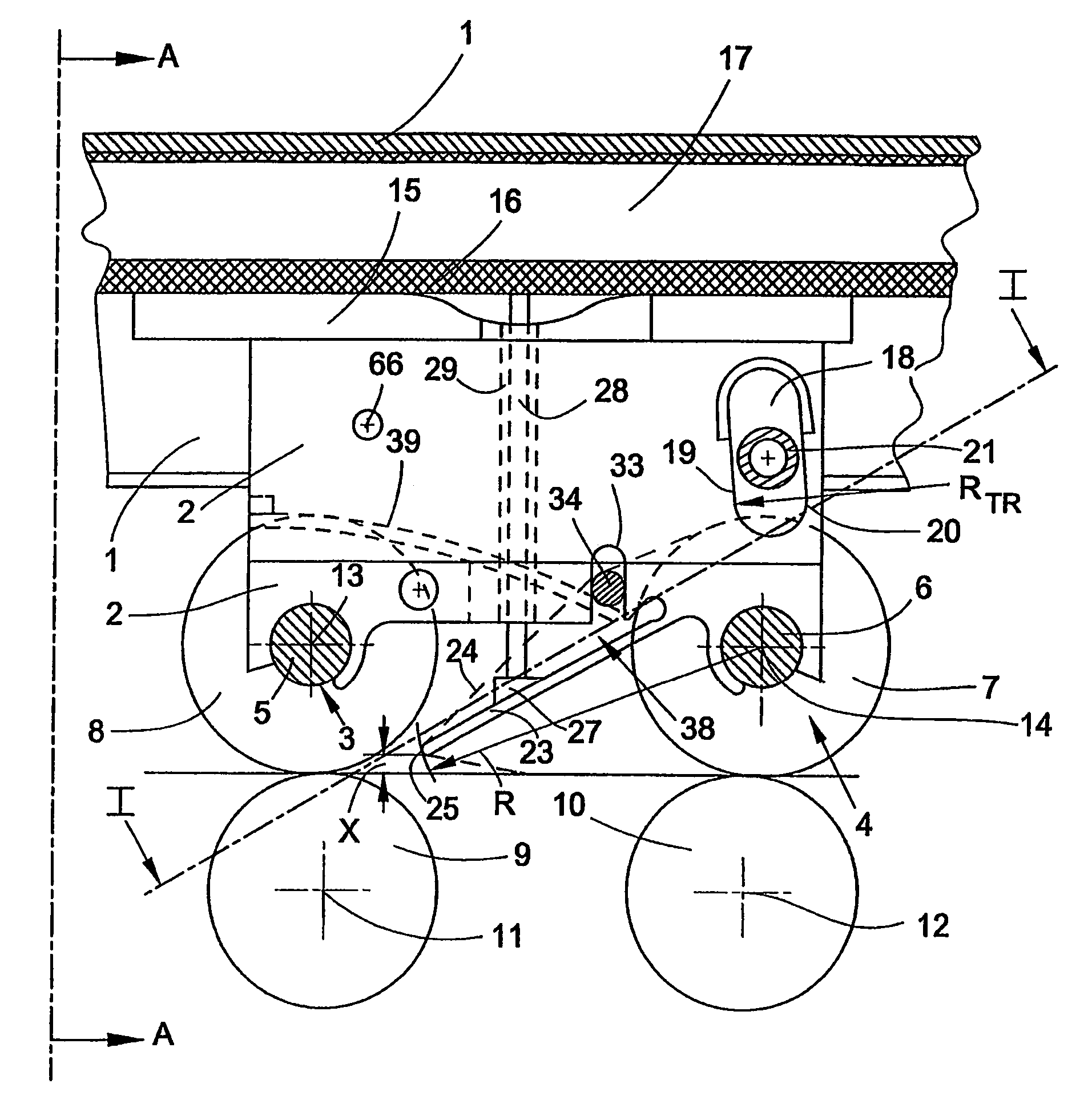
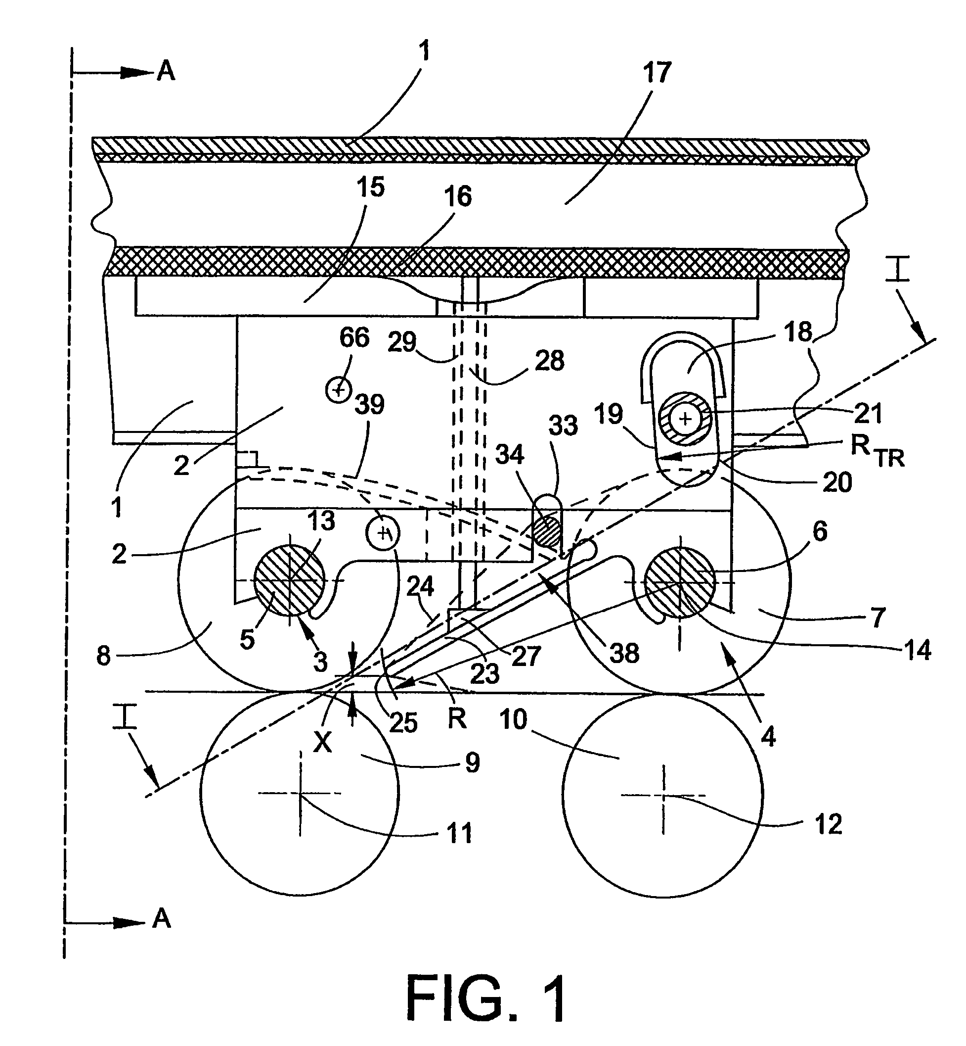
[0016]The holding device according to the invention movably connected to the top roller carrier combines the axle receivers for the output roller and the apron roller in one component. The position of the axle receivers in the holding device and therefore the position of the axles of the output roller and the apron roller with respect to one another can be produced with a high degree of manufacturing precision. In this manner, an extraordinarily exact positioning of the clamping points of the apron roller and output roller can be achieved and maintained. The parallelism of the output roller and apron roller is always ensured. The addition of conventional safety spacings can be dispensed with. Such conventional safety spacings are taken into account, for example, in the adjustment of the desired field width, because the achievable accuracy in the field width adjustment can only be inadequate. Manufacturing and assembly inaccuracies, which can add up with multi-part holders, allow an oblique position of the top rollers, which disadvantageously influences the adjustment of the field widths. Additions in the form of safety spacings are to counteract this. The holding device according to the invention reduces the number of components for the holding device compared to conventional holding devices. In order to be able to load the holding device with a force in the direction of the bottom rollers, only a single common mechanism, for example a spring mechanism, is necessary. The force loading of the output roller and apron roller can take place separately from other top rollers like the feed roller. The outlay occurring during a change in the significant field width adjustment between the apron roller and feed roller is small. The outlay required during production and assembly is lowered as less and only simpler parts are required.
[0023]A holding device consisting of plastics material can be produced particularly economically, has only a low weight, is resistant to corrosion and satisfies the elasticity demands on the holding device. Polyoxymethylene, designated POM, is distinguished by a high degree of hardness, stiffness and toughness and is particularly suitable for this application. If the plastics material is electrically conductive, an uncomplicated discharge of electrostatic charges is ensured. Thus disturbances in the spinning operation caused by electrostatic charge are avoided.

Problems solved by technology

Such conventional safety spacings are taken into account, for example, in the adjustment of the desired field width, because the achievable accuracy in the field width adjustment can only be inadequate.
Manufacturing and assembly inaccuracies, which can add up with multi-part holders, allow an oblique position of the top rollers, which disadvantageously influences the adjustment of the field widths.

Method used


Image

  • Top roller carrier for drafting systems in spinning machines
  • Top roller carrier for drafting systems in spinning machines
  • Top roller carrier for drafting systems in spinning machines

Examples


Embodiment Construction

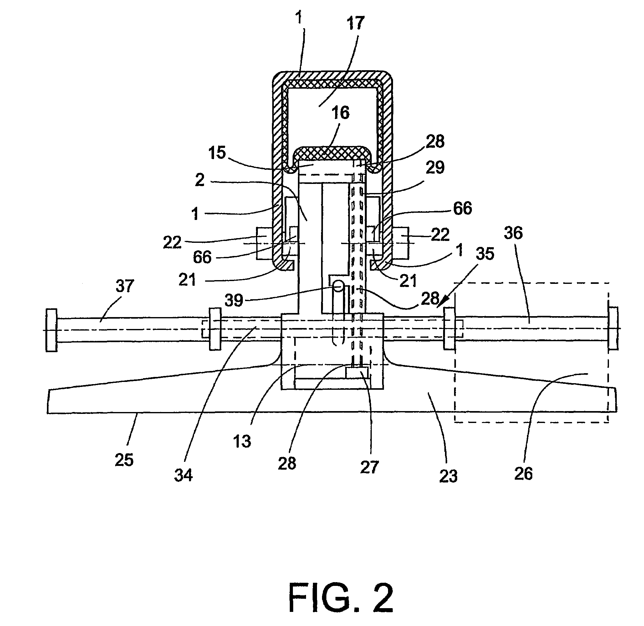
[0032]FIG. 1, shows a part of a top roller carrier 1, which carries a holding device 2. Top roller carriers of this type are used on drafting systems of spinning machines. The holding device 2 has axle receivers 3, 4 for the axles 5, 6 of the pair of apron rollers and the pair of output rollers. The position of the pair of apron rollers and the pair of output rollers is indicated in each case by an apron roller 7 and an output roller 8. The two axle receivers 3, 4 are part of the one-piece holding device 2. The holding device 2 consists of the elastic plastics material POM. Because of the elasticity, the axles 5, 6 can be pressed in a simple manner into the axle receivers 3, 4 during assembly. The axles 5, 6 are reliably held in the snap-on connection. The pair of apron rollers and the pair of output rollers together with the pair of feed rollers, not shown in FIG. 1, form the top rollers of the drafting system. The associated bottom rollers 9, 10 are positioned in such a way that t...


PUM

PropertyMeasurementUnit
tensionaaaaaaaaaa
electrically conductiveaaaaaaaaaa
lengthaaaaaaaaaa

Abstract

A top roller carrier for drafting systems in spinning machines with at least one pair of feed rollers, one pair of apron rollers and one pair of output rollers as top rollers and with holding devices for the top rollers, and wherein the top rollers are rotatably mounted on the ends of axles which are held centrally between the top rollers. According to the present invention, a common holding device is provided for the axle of the output rollers and the axle of the apron rollers and is movably connected to the top roller carrier and fixes the two axles at a rigid spacing with respect to one another.

Description

CROSS-REFERENCE TO RELATED APPLICATIONS[0001]This application claims the benefit of German patent application 10 2005 005 382.3, filed Feb. 5, 2005, herein incorporated by reference.FIELD OF THE INVENTION[0002]The invention relates to a top roller carrier for drafting systems in spinning machines and, more particularly, to a top roller carrier with at least one pair of feed rollers, one pair of apron rollers and one pair of output rollers as top rollers and with holding devices for the top rollers, wherein the top rollers are rotatably mounted on the ends of axles which are held centrally between the top rollers.BACKGROUND OF THE INVENTION[0003]Top roller carriers are generally used as a carrying and loading arm for pairs of top rollers and can be lifted relative to the bottom rollers mounted so as to be secured to the machine.[0004]In drafting systems, it is known to carry out an adaptation, which is necessary for reasons concerning textile technology, to the fibre material or the ...

Claims


Application Information

Patent Timeline
Patent Type & Authority Patents(United States)
IPC IPC(8): D01H5/46
CPCD01H5/44D01H5/86D01H5/565
Inventor WINTER, JOSEF
Owner SAURER COMPONENTS GMBH
Learn More