Convergent divergent nozzle with supported divergent seals

a divergent nozzle and divergent technology, applied in vessel construction, marine propulsion, aircraft navigation control, etc., can solve problems such as restricting the area ratio range, and achieve the effect of reducing the radar cross section

Active Publication Date: 2009-12-01
RTX CORP
View PDF7 Cites 11 Cited by
  • Summary
  • Abstract
  • Description
  • Claims
  • Application Information

AI Technical Summary

Benefits of technology

[0013]By having the forward bridge bracket retain the divergent seal in the axial direction, there is no need for axial sliding of the divergent seal relative to the divergent flap. A horn is mounted adjacent an aft end of the convergent seal. A fork is mounted adjacent the forward end section of the divergent seal. The fork includes a spline arranged on either side of the longitudinal axis. The horn extends between the splines and need only provide circumferential support as the axial and radial support are provided by the sliding interface between the forward seal bridge bracket, the aft seal bridge bracket and the respective forward bridge support and aft bridge support. Such an interface permits the forward end section of the divergent seal and the forward end section of the divergent flap to include a radiused surface which provide a smooth interior interface between the convergent section and the divergent section which significantly reduces radar cross section when a radar beam is directed toward the rear of the nozzle system.

Problems solved by technology

Disadvantageously, the interfaces between flaps and / or between flaps and seals which permit the necessary flexibility may also restrict the area ratio range.

Method used


Image

  • Convergent divergent nozzle with supported divergent seals
  • Convergent divergent nozzle with supported divergent seals
  • Convergent divergent nozzle with supported divergent seals

Examples


Embodiment Construction

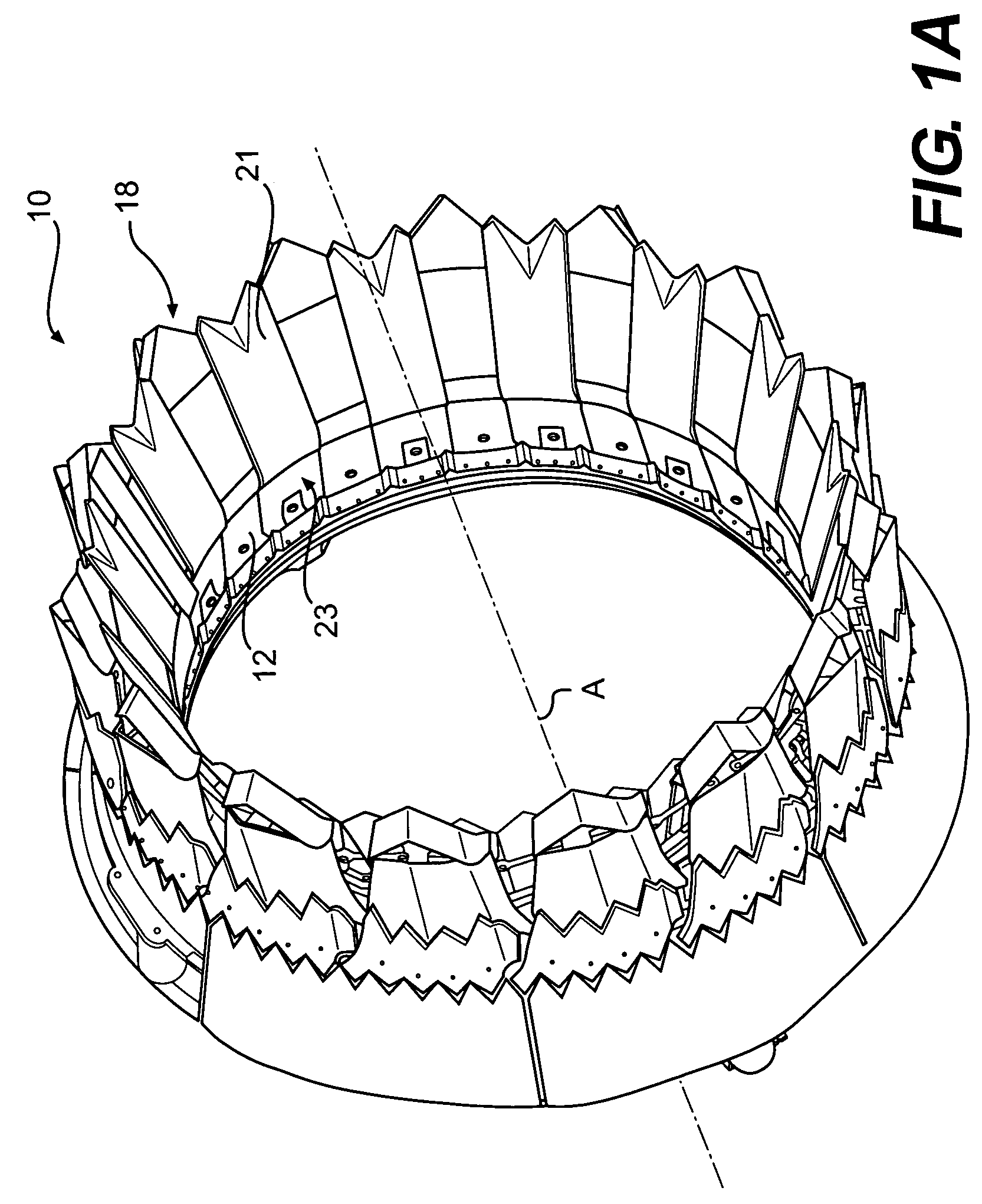
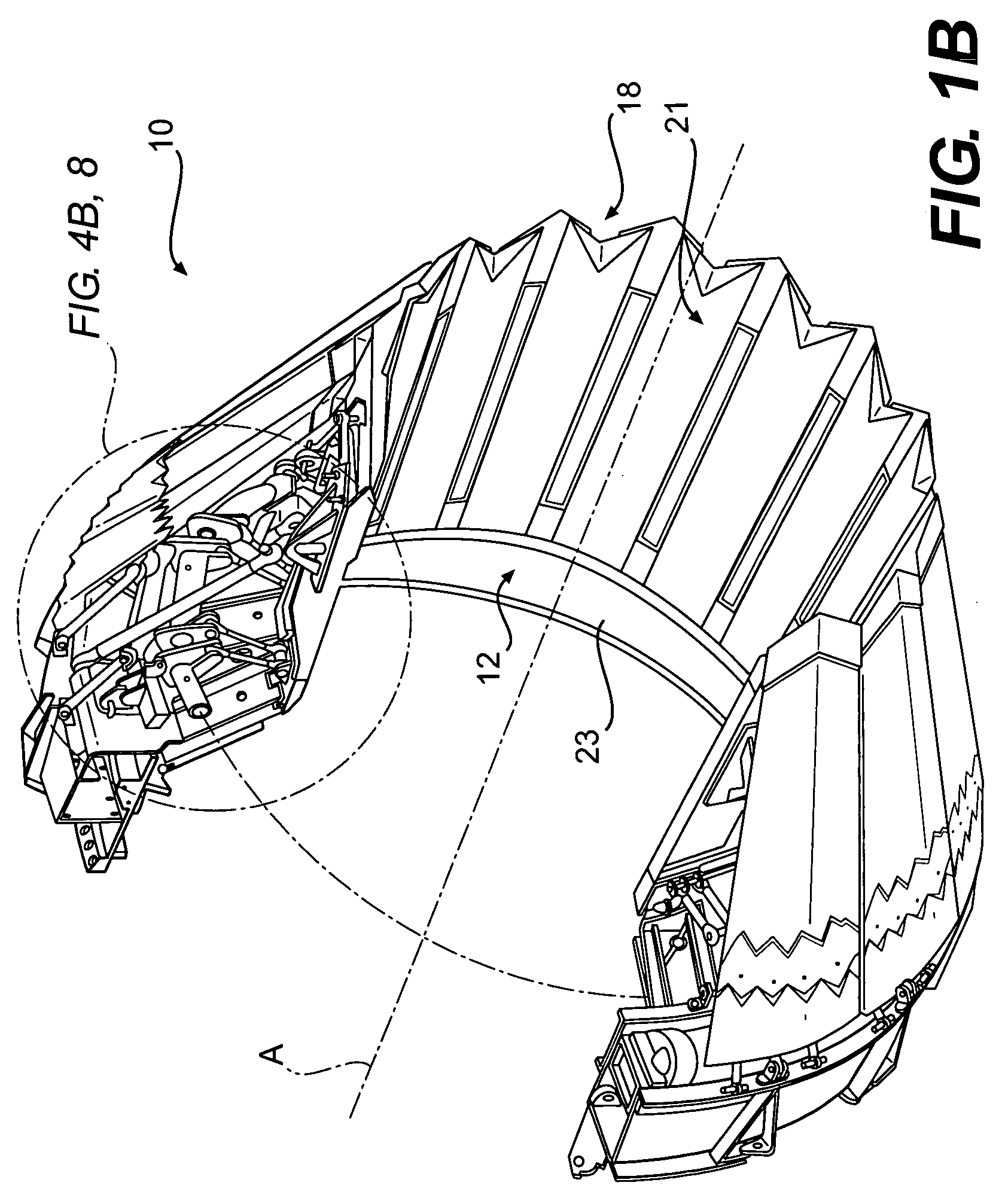
[0029]FIGS. 1A and 1B illustrate a nozzle system 10 for a gas turbine engine. FIG. 1A depicts the nozzle 10 in a maximum dilated position (also illustrated in FIG. 2A), which is typical during afterburning operation, and FIG. 1B depicts the nozzle system 10 in a minimal dilated position (FIG. 2B), which is typical during non-afterburning operation.

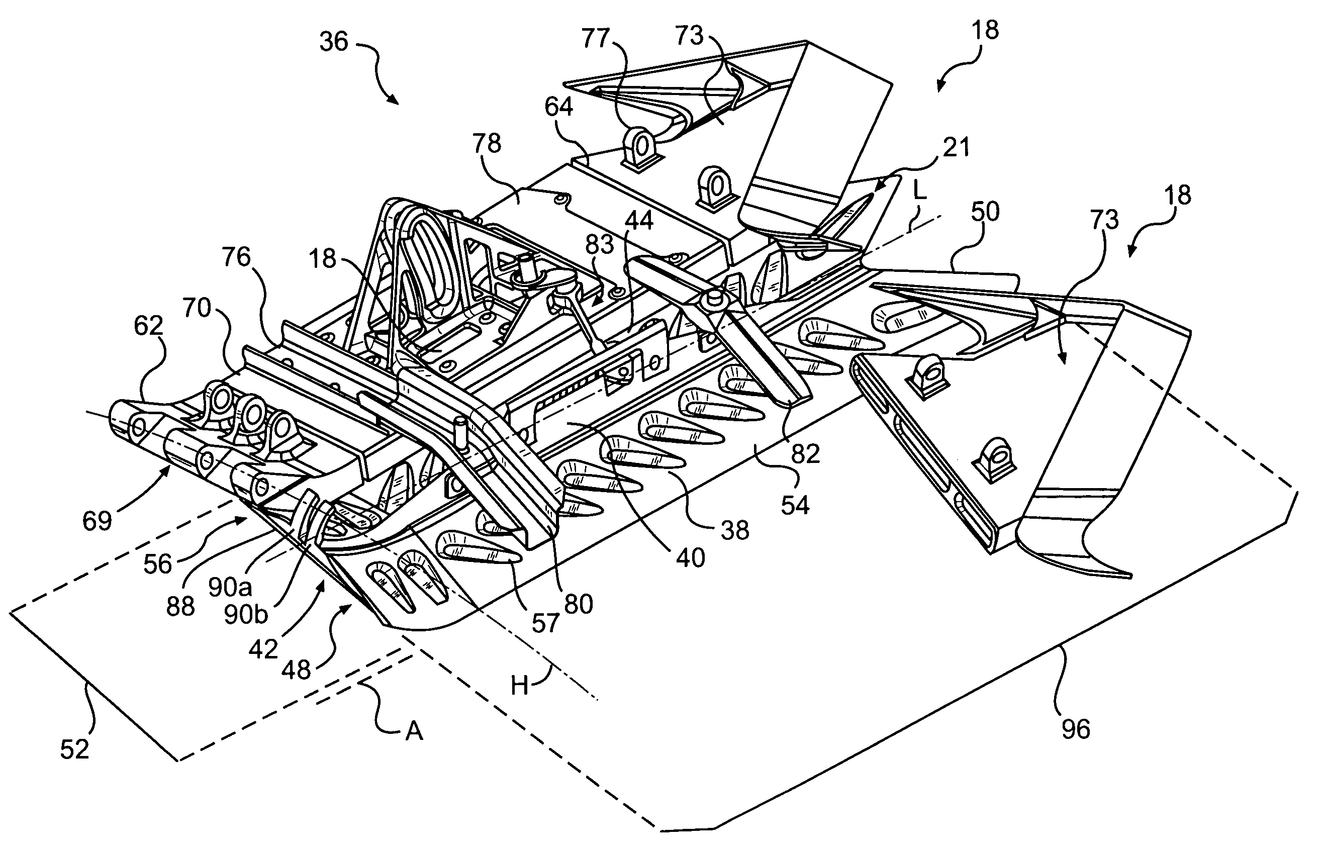
[0030]Referring to FIGS. 2A and 2B, the nozzle includes a plurality of circumferentially distributed convergent flaps 12 (only one shown in section), each pivotably connected to a stationary frame 14 with a cooling liner panel 16 upstream thereof. A plurality of circumferentially distributed divergent flaps 18 (only one shown in section) are pivotably connected at a joint structure 20 to an aft end section of the convergent flaps 12.

[0031]A plurality of divergent seals 21 (FIGS. 4A and 4B) are each pivotally connected to a respective convergent seal 23 which are respectively distributed circumferentially between each of the divergent flap ...


PUM


Abstract

A nozzle system includes a multitude of circumferentially distributed divergent seals that circumscribe an engine centerline. Each divergent seal includes an interface between a forward seal bridge bracket and an aft seal bridge bracket with a forward bridge support and an aft bridge support which provides axial and radial support for the divergent seals between adjacent divergent flaps. A divergent-convergent seal joint structure includes a horn and a fork. By having the forward bridge bracket retain the divergent seal in the axial direction, there is no need for axial sliding of the divergent seal relative to the divergent flap. The joint structure provides circumferential support as the axial and radial support are provided by the bridge-bracket interface. The joint interface permits the forward end section of the divergent seal and the forward end section of the divergent flap to include a radiused surface which provides a smooth interior interface between the convergent section and the divergent sections.

Description

[0001]This invention was made with government support under Contract No.: N00019-02-C-3003 with the Department of Navy. The government therefore has certain rights in this invention.BACKGROUND OF THE INVENTION[0002]The present invention relates to gas turbine engines having convergent / divergent nozzles, and more particularly to divergent seals for such a nozzle system.[0003]A variable area exhaust nozzle optimizes the thrust produced within a gas turbine engine. In augmented gas turbine engines, convergent / divergent (C / D) nozzles provide a multitude of nozzle positions. The term “convergent-divergent” describes an exhaust nozzle having a convergent section upstream of a divergent section. Exhaust gases exiting the turbine(s) pass through the decreasing diameter convergent section before passing through the increasing diameter divergent section.[0004]The convergent section is pivotally connected to the exhaust duct and to the divergent section. The divergent section is pivotally conn...

Claims


Application Information

Patent Timeline
Patent Type & Authority Patents(United States)
IPC IPC(8): F02K1/12
CPCF02K1/12F02K1/805F02K1/1223
Inventor PETERS, DONALD W.
Owner RTX CORP
Why Eureka
Try Eureka