Facing having increased stiffness for insulation and other applications

a technology of stiffening and insulation, applied in the direction of heating and cooling equipment, other domestic objects, lighting and heating apparatus, etc., can solve the problems of affecting the application of the product to the insulation covered conduit, the prefabrication of the metal sheets at the factory into the desired shape and size is very time-consuming and thus expensive, and the subsequent application of the product is also a time-consuming process. , to achieve the effect of easy application, good appearance and easy cutting and manipulation

Inactive Publication Date: 2009-12-01
3M INNOVATIVE PROPERTIES CO
View PDF37 Cites 32 Cited by
  • Summary
  • Abstract
  • Description
  • Claims
  • Application Information

AI Technical Summary

Benefits of technology

[0011]This invention relates generally to a facing material for application to exposed surfaces of insulation or other like materials to provide a vapor seal and to protect the insulation from weather-related damage. The facing of this invention overcomes the drawbacks of the prior art systems discussed above, since it is relatively inexpensive, is easy to apply, provides a good appearance, is easily cut and manipulated at the job site, and provides substantially a 100% vapor seal. The facing of this invention can be molded manually to conform to the shape of the surface being covered, and the facing will retain that shape once molded. The facing of this invention also can be applied and will maintain its integrity in extreme weather conditions and is very fire-resistant.

Problems solved by technology

However, sheet metal facing has certain drawbacks.
In the first place, the prefabrication of these metal sheets at the factory into a desired shape and size is very time-consuming and thus expensive.
The subsequent application of these products to the insulation covered conduits is also a time-consuming process.
The metal facing also can be very heavy and therefore difficult to handle and manipulate at the jobsite.
In addition, the resulting sheet metal facing has a large number of joints which often are not completely sealed and which permit water to pass therethrough and thereby to wet the insulation.
This wetting of the insulation is undesirable, and can result in corrosion of the underlying equipment and conduits.
Any repair work can be quite costly and time-consuming.
However, this solution also has drawbacks including the fact that the butyl rubber does not perform well and has a poor appearance.
Butyl rubber is also very difficult to apply because it is messy to cut and form, and it is very heavy.
Butyl rubber has also been known to cause delamination of the outer surface of the insulation from the fiberglass or the wool disposed in the interior of the insulation, because of its weight and because of its lack of strength at elevated temperatures.
Butyl rubber also tends to creep, has poor fire and smoke ratings and therefore is not UL listed.
However, such coverings have little or no puncture resistance, and the butyl rubber adhesive layer has the same drawbacks noted above for butyl rubber facing, including a tendency to run or ooze at elevated temperatures.
However, the use of such materials is often very labor-intensive and requires a multiple step process.
These products can only be applied during certain weather conditions, and it is very difficult to regulate the thickness of mastic to make it uniform.
Consequently, such products have very limited applications and generate a poor appearance.
This product is very labor-intensive to apply and is not recommended for exterior use.
It also has a very poor fire rating and is unsightly.
Its use, therefore, is very limited.

Method used


Image

  • Facing having increased stiffness for insulation and other applications
  • Facing having increased stiffness for insulation and other applications
  • Facing having increased stiffness for insulation and other applications

Examples


Embodiment Construction

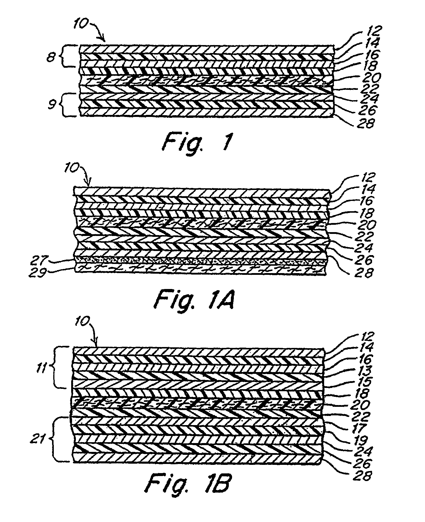
[0029]With reference now to the drawings, and more particularly to FIG. 1 thereof, one embodiment of the facing 10 of this invention will be described. Facing 10 includes a central layer, which may be a layer of fabric, and, on each side of the central layer, a structure having alternating layers of a metal-containing foil and a puncture-resistant polymer film bonded to the central layer by an extrusion layer. The layers of foil in the structure provide the desired vapor seal, weather resistance, and a desirable exterior appearance. The layers of polymer in the structure provide puncture and tear resistance, particularly with respect to birds and other animals. The central layer provides additional tear resistance, strength, and a desired textured appearance. The extrusion layers provide further strength. All of these layers of material together provide the desired fire resistance and resistance to flame spread. The central and extrusion layers together also provide additional stiff...


PUM

PropertyMeasurementUnit
thicknessaaaaaaaaaa
total thicknessaaaaaaaaaa
thicknessaaaaaaaaaa

Abstract

A covering for exposed insulation surfaces on fluid conduits for protection from moisture and other environmental factors. The covering typically includes a central fabric layer, such as a woven high density polyethylene fabric surrounded by structures having layers of alternating metal containing foils and puncture resistant polymers. The structures may be bonded to the central fabric layer by a polymer extrusion, such as a low density polyethylene extrusion. An acceptable metal-containing foil may includes aluminum foil, and the puncture resistant polymer may be polyester. The resulting covering may be cut with a hand-held implement, such as scissors or a knife or the like, may be formed into desired shapes manually and will retain the desired shape once formed. The overall thickness of the covering typically is no greater than about 350 microns.

Description

RELATED APPLICATIONS[0001]This application claims the benefit under 35 U.S.C. § 120 and is a continuation of U.S. application Ser. No. 10 / 737,522 entitled “Facing For Insulation And Other Applications,” filed on Dec. 16, 2003, now abandoned which is a continuation of application Ser. No. 10 / 731,847 entitled “Facing For Insulation And Other Applications,” filed on Dec. 9, 2003, now abandoned which is a continuation-in-part of U.S. application Ser. No. 10 / 330,162, entitled “Facing For Insulation And Other Applications,” filed on Dec. 27, 2002, now abandoned all of which are incorporated herein by reference in its their entirety.FIELD OF THE INVENTION[0002]This invention relates generally to insulation products for use with fluid conduits, such as pipes or ducts, and more particularly to a stiffened facing material for insulation surrounding fluid conduits for providing a vapor barrier and a weather seal.BACKGROUND OF THE INVENTION[0003]Pipes or ductwork in dwellings, commercial buildi...

Claims


Application Information

Patent Timeline
Patent Type & Authority Patents(United States)
IPC IPC(8): F16L9/14B31F1/00B32B7/02B32B7/12B32B15/08B32B15/20F16L59/08
CPCB32B15/08F24F13/0263F16L59/08C09J2400/163C09J2400/226B32B1/08C09J2301/122C09J2301/302B32B7/12B32B5/024B32B2307/558B32B2307/732B32B27/36B32B15/20B32B27/12B32B2262/0253B32B5/022B32B2597/00B32B2262/101B32B15/09B32B2571/00B32B27/32B32B2311/24B32B2305/188B32B2307/7246B32B2307/71B32B2307/712B32B2323/046B32B2367/00
Inventor COHEN, LEWIS S.VAN BEUKERING, SEBASTIANUS FRANCISCUS MARIAWYER, STEVEN
Owner 3M INNOVATIVE PROPERTIES CO
Why Eureka
Try Eureka