Method and apparatus for three-dimensional optical scanning of interior surfaces

a three-dimensional optical scanning and interior surface technology, applied in the field of high-precision three-dimensional replicas, can solve the problems of irritability, acoustic feedback, and possibly infection of the epidermis of the ear canal, and systematic or random errors in the calibration and/or performance of scanners for these uses can be fatal, and limit the use of scanning in the modelling of such implants and shells. , to achieve the effect of easy production of complex models

Inactive Publication Date: 2009-12-01
3SHAPE AS
View PDF84 Cites 225 Cited by
  • Summary
  • Abstract
  • Description
  • Claims
  • Application Information

AI Technical Summary

Benefits of technology

[0022]Compared to prior art scanners this scanner has the advantage that it is able to cover the whole circumference without moving the scanner thus being able to scan the whole inner surface of an object. With this layout it is possible to scan interior surfaces such as the ear canal, tubes, pipes and bores with non-contact scanning and obtain high precision scan data of the whole interior surface of the object.
[0024]According to an especially preferred embodiment the scanner is equipped with a position sensor, which allows the relative position and orientation of the scanner and the object to be determined for successive scans. This greatly facilitates the combination of data from successive scans and makes it possible to combine these with much higher precision irrespective of the position and orientation of the scanner during scanning.
[0026]The compact layout of the scanner allows for easy scanning of interior surfaces of objects of extremely small size. The ease of operation of the scanners according to the invention means that practitioners without experience in scanning can easily perform the scanning operations, which is required especially in the case of scanning of body cavities and scanning for archaeological purposes.
[0032]The method allows for easy scanning of interior surfaces of objects which cannot be scanned with high precision using prior art scanning methods.
[0040]Once the data are recorded the piece may be manufactured using any automatic manufacturing technique such as milling. More preferably the modelling technique comprises 3-dimensional printing, stereo lithography, selective laser sintering, laminated object modelling, inkjet modelling, fused deposition modelling, nano-printing. A common feature of these techniques is that only the required amount of material is used and that it is easier to produce complex models such as devices for the ear and / or ear canal and / or dental implants.

Problems solved by technology

For hearing aid shells sub-millimeter precision is required or the shell will cause irritation, acoustic feedback and possibly infection to the epidermis of the ear canal.
Therefore systematic or random errors in the calibration and / or performance of scanners for these uses can be fatal.
This has hitherto limited the use of scanning in the modelling of such implants and shells.
The disclosed scanner is not adapted to scan interior surfaces due to its size and due to the fact that the light sources point towards the centre of in which the object to be scanned must be placed.
This scanner thus suffers from the same occlusion effects as non-portable scanners.
However the scanner only rotates the light deflecting means and not the construction related to the detector, which only makes it able to scan a very limited part of the circumference.
It is however doubtful whether the profiler can measure the dimensions precisely, since small errors in the orientation of the profiler along the axis of the pipe or tube will cause the disc to be distorted.
Due to this construction, the angle at which light is reflected from the surface towards the camera is very small and not optimal for precision scanning.
Furthermore, the scanner is only adapted to map small areas.
Additionally the design is very likely to give very distorted images, which makes high precision scanning infeasible.
However the scanner is only able of perform scans at maximal 180° of the circumference, since it only applies one or two static coplanar mirrors.
Furthermore, the disclosure fails to take regard to the fact that the individual is likely to move while the images are recorded.
One disadvantage of the system is the need for filling the patient's ear completely with water.
This can be extremely annoying to patients and they may experience symptoms of nausea during and after such treatment.
Furthermore it is doubtful whether it is really possible to determine the three dimensional co-ordinates of the surface of the ear canal with the required precision using an ultra sonic scanner.
It must be extremely difficult for the underlying software to determine which of the signals to use in the determination of the co-ordinates.

Method used


Image

  • Method and apparatus for three-dimensional optical scanning of interior surfaces
  • Method and apparatus for three-dimensional optical scanning of interior surfaces
  • Method and apparatus for three-dimensional optical scanning of interior surfaces

Examples


Embodiment Construction

[0056]Further scope of applicability of the present invention will become apparent from the detailed description given hereinafter. However, it should be understood that the detailed description and specific examples, while indicating preferred embodiments of the invention, are given by way of illustration only, since various changes and modifications within the spirit and scope of the invention will become apparent to those skilled in the art from this detailed description.

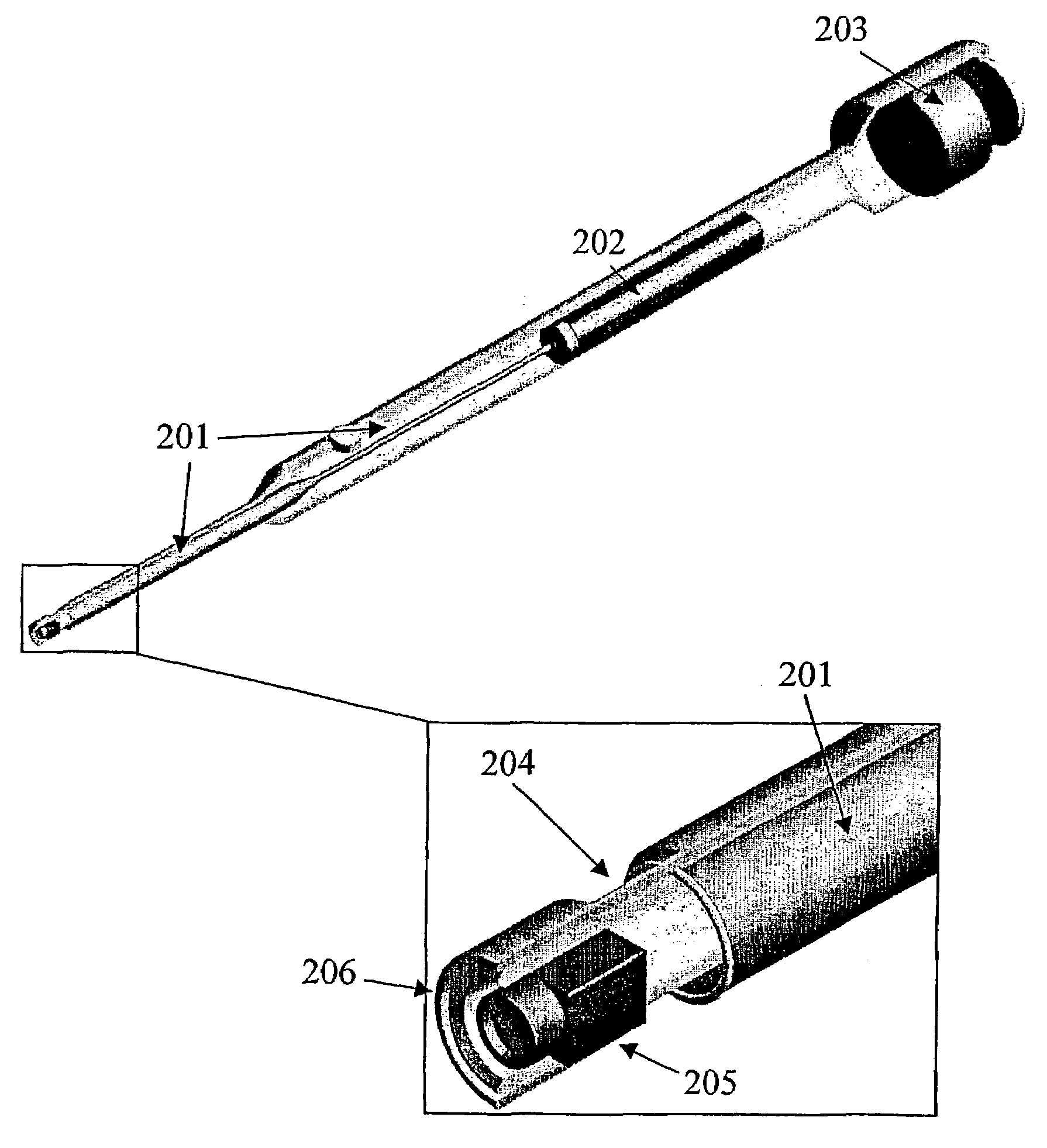
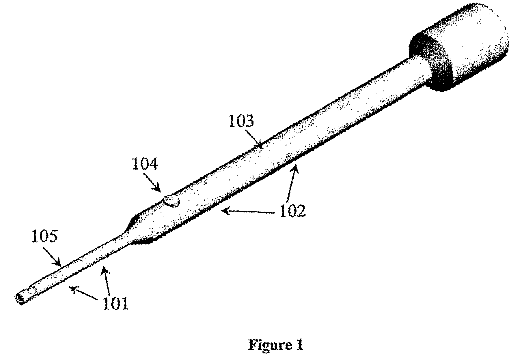
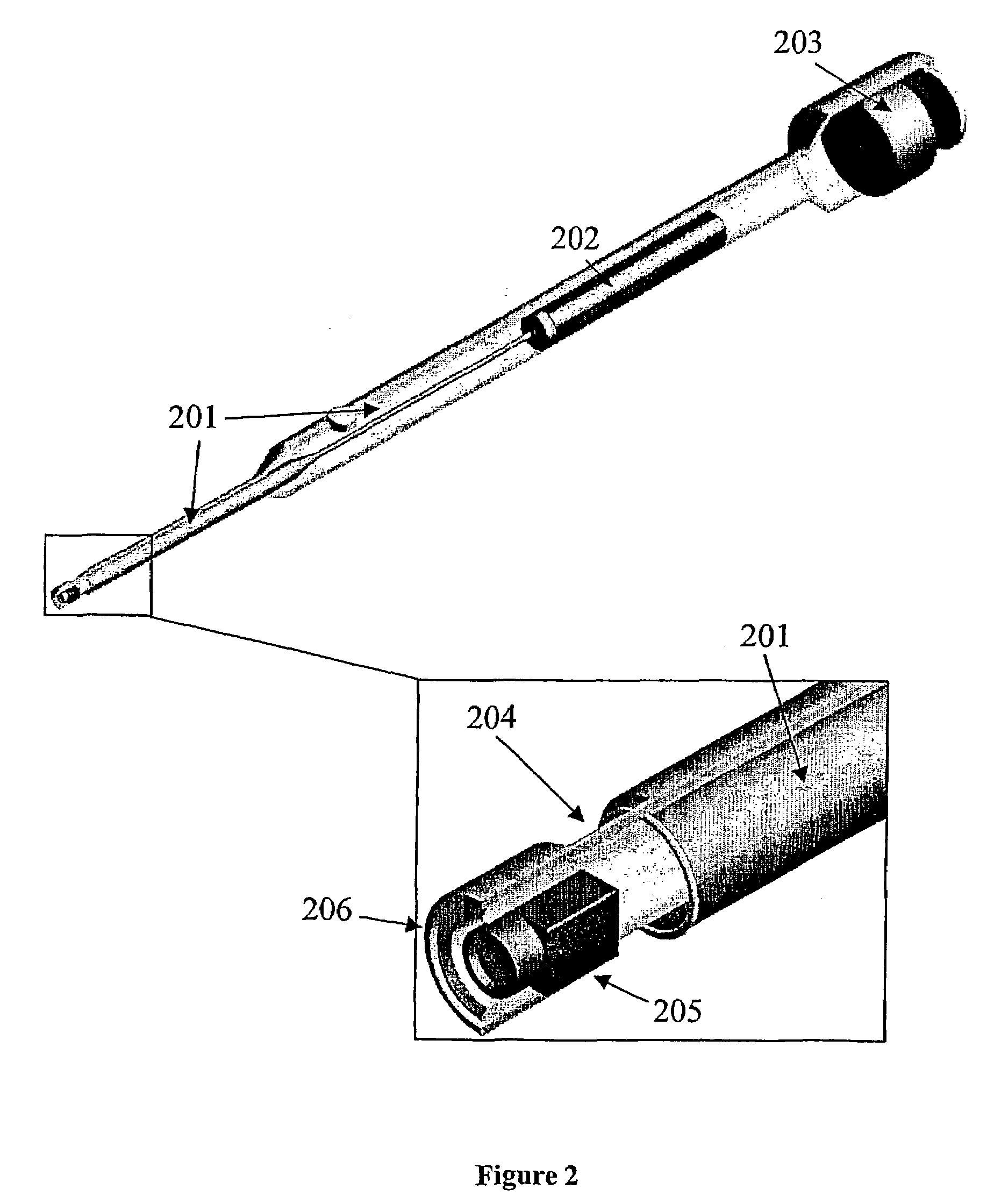
[0057]FIG. 1 to FIG. 4 illustrate two preferred embodiments of the invention. The first part 101 of the scanner is the probe, which is inserted into the cavity. The second part 102 is a handle. The scanner in FIG. 1 and FIG. 2 comprises a cover 103, a scan button 104, a disposable cover 105, light guides 201, a light source 202, a position sensor 203, optics and mirrors and / or prisms 204, a camera 205 and a protector / collision detector 206. A rotating mirror and / or prism with a micro motor 301 is also added to th...


PUM


Abstract

A scanner for three-dimensional scanning of interior surfaces or cavities of limited dimensions or with restricted accessibility. The scanner includes a probe having an axis and at least one light source and one camera adapted to perform a scan 360° around the axis of the probe. High precision three-dimensional replicas of real objects may be created using 3-D scan data obtainable with the scanner.

Description

[0001]This is a nationalization of PCT / DK01 / 00561 filed Aug. 24, 2001 and published in English.TECHNICAL FIELD[0002]The invention relates to the creation of high precision three-dimensional replicas of real objects. The invention specifically concerns the three-dimensional scanning of interior surfaces or cavities of limited dimensions or with restricted accessibility. Furthermore, the invention relates to a specific embodiment for scanning the human ear and ear canal.PRIOR ART[0003]Systems for three-dimensional optical scanning are well known in the prior art. They typically comprise one or more light sources projecting a structured light pattern on the object to be scanned, one or more cameras and data processing equipment to convert the recorded image co-ordinates to three dimensional co-ordinates using state of the art software. Usually, only a part of the object is scanned in a single scan. To create a full scan the object, camera and light source need to be move relative to ea...

Claims


Application Information

Patent Timeline
Patent Type & Authority Patents(United States)
IPC IPC(8): A61B1/00A61B1/04A61B1/05A61B1/227A61B5/107G01B3/30G01B11/24G01B11/25
CPCA61B1/05A61B1/227G01B11/25G01B3/30G01B11/24A61B5/1076B33Y50/00B33Y80/00A61B1/0605
Inventor DEICHMANN, NIKOLAJCLAUSEN, TAISFISKER, RUNEVASILJEV BARTHE, CHRISTOPHE
Owner 3SHAPE AS
Why Eureka
Try Eureka