
Tissue fusion/welder apparatus and method

a tissue fusion and welding apparatus technology, applied in the field of surgical devices, can solve the problems of not being able and unable to achieve the effect of reducing the number of surgical operations

Inactive Publication Date: 2009-12-01
APPL MEDICAL RESOURCES CORP
View PDF35 Cites 1366 Cited by
  • Summary
  • Abstract
  • Description
  • Claims
  • Application Information

AI Technical Summary

Benefits of technology

The present invention is a device and method for emulating the mechanical fixation of tissue. It creates small welds in tissue and cuts relative to the welds using a heated instrument. The device has an elongated shaft with jaws that can be connected in different configurations for heating the tissue. The jaws have electrodes that push through the tissue and provide electrical continuity. The resulting weld is continuous through the layers of tissue and resembles a rivet. The device can be used multiple times, overcoming the limitations of existing devices. Overall, the invention provides a more efficient and effective way to fix tissue.

Problems solved by technology

As one would imagine, it is not desirable to over-compress tissue or develop a condition where required nourishment to tissue is compromised.
If too many staples are placed or if the staples are over-compressed, the included tissue may be deprived of nutrition and may subsequently necrose and cause serious complications.
In addition, staples are typically formed of a material which is foreign to the body and may cause responses that will further complicate recovery or healing.
Staples cannot be cut through or removed easily.
Staples also cause problems with imaging technologies.
However, they often require prior preparation from autologous materials.
In addition, they do not have the full confidence of the medical community.
This technique has proved to be relatively effective in small vessels; however, large vessels are not indicated for this approach.
The relationship between the diameter of the vessel and the wall thickness has proven to be the limiting factor in tissue fusion and welding in most cases.
However, the ESE is not effective to divide and provide hemostasis or fluid stasis in large vessels or conduits.
While the ESE has been well adapted to seal small capillaries, it has not been effective to shut-off the fluid flow in a large conduit.

Method used


Image

  • Tissue fusion/welder apparatus and method
  • Tissue fusion/welder apparatus and method
  • Tissue fusion/welder apparatus and method

Examples


Embodiment Construction

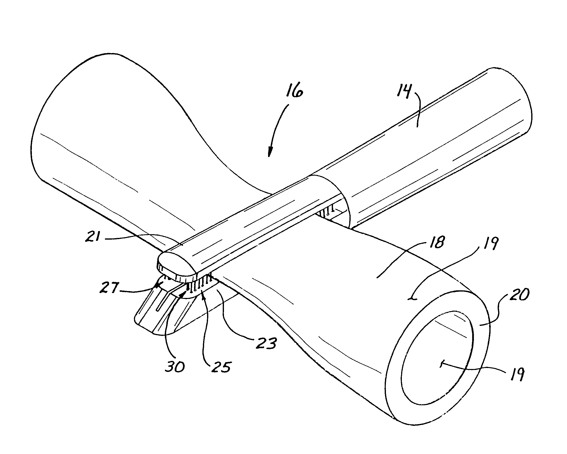
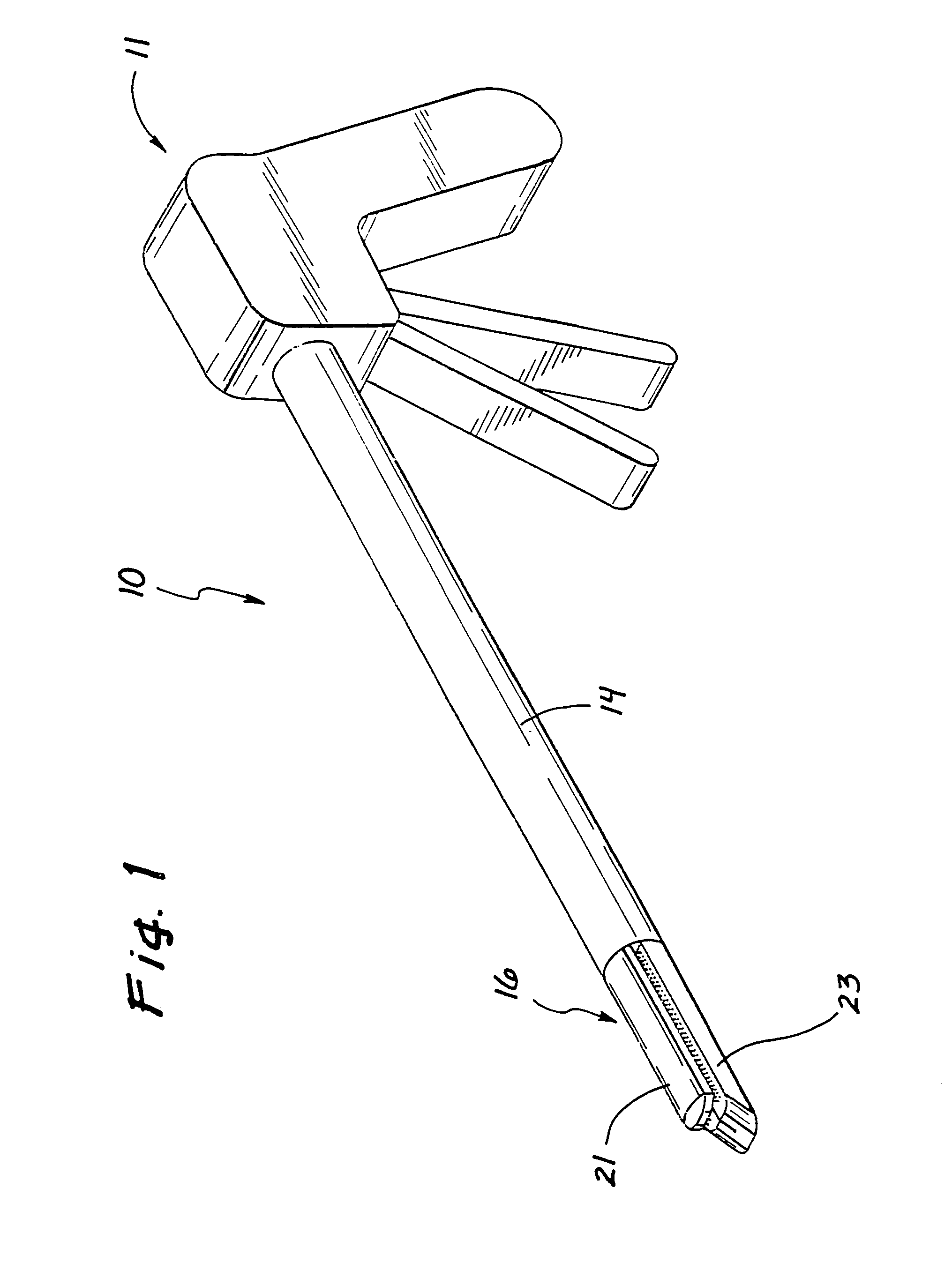
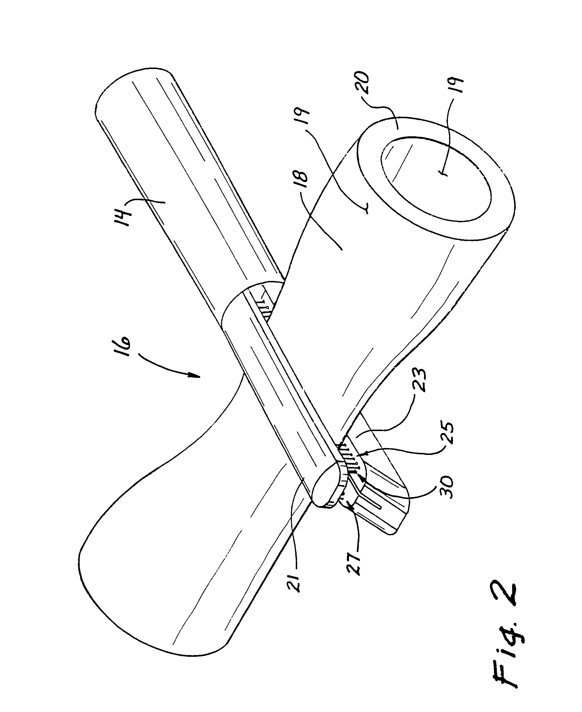
[0067]With reference to the drawings of FIGS. 1 and 2, a tissue welder 10 in one embodiment of the present invention is shown to include a handle 11, and an elongate shaft 14, and a distal portion 16. This distal portion 16 includes a pair of opposing jaws 21 and 23 which are adapted to compress tissue 18, having outer surfaces 19 that define deep inner portions 20.

[0068]In the illustrated example, the compressed tissue 18 has the configuration of a tube where one side of the tube is compressed into a surface proximate relationship with the other side of the tube in order to occlude the tube. It will be appreciated that the invention is equally adapted to bond any two pieces of tissue disposed in a tissue proximate relationship.

[0069]One of the opposed jaws 21 is configured to have a plurality of penetrating members or needles 25. The opposite jaw 23 provides a stop or a contact member against which the penetrating members 25 can be moved. Energy is delivered to, and through, the pe...


PUM


Abstract

A tissue welding apparatus is adapted to fuse a first piece of tissue to a second piece of tissue which are disposed in a surface proximate relationship. An elongate shaft carries a first jaw, and a second opposing jaw moveable relative to the first jaw. At least one penetrating member is carried by the first jaw and moveable relative to the second jaw to create a channel through the first piece of material and the second piece of material. A source of heat is coupled to the penetrating member for denaturing the tissue defining the channel. This denatured tissue forms a column binding the first piece of tissue to the second piece of tissue. A chemical agent can be carried to the tissue with the penetrating member.

Description

BACKGROUND OF THE INVENTION[0001]1. Field of the Invention[0002]This invention generally relates to surgical devices and, in particular, to an apparatus and method for fusing and / or welding tissue.[0003]2. Discussion of Related Art[0004]Surgery generally involves the cutting and fixing of tissue. The cutting is usually undertaken in one of two modalities, either cold cutting or hot cutting. Cold cutting is performed using a mechanical device such as a knife or scissors. Hot cutting involves the use of high frequency electrosurgical current, ultrasonic sound or heat. The fixation of cut tissue commonly involves the use of sutures, staples or clips. More recently, tissue adhesives have evolved as an occasional alternative.[0005]The process of inhibiting blood flow from cut or severed tissue, commonly referred to as hemostasis, is often undertaken using power generated by an electrosurgical device. Various electrosurgical effects can be achieved, such as coagulation, fulguration and ca...

Claims


Application Information

Patent Timeline
Patent Type & Authority Patents(United States)
IPC IPC(8): A61B18/18A61B17/08A61B17/12A61BA61B17/00A61B17/32A61B18/04A61B18/12A61B18/14
CPCA61B17/12013A61B18/1442A61B18/1445A61B18/1477A61B2017/320052A61B2018/1455A61B2018/00601A61B2018/0063A61B2018/1412A61B2018/1425A61B2018/143A61B2018/00404
Inventor HART, CHARLES C.JOHNSON, GARY M.HILAL, SAID S.BRUSTAD, JOHN R.PINGLETON, EDWARD D.
Owner APPL MEDICAL RESOURCES CORP
Learn More