Inlet system for an MOCVD reactor

a mocvd reactor and inlet system technology, applied in the direction of polycrystalline material growth, crystal growth process, chemically reactive gas growth, etc., can solve the problems of undesired increase of gas inlet zone in this way, and the latter is undesired, so as to reduce the horizontal extent of inlet zone, and increase flow velocity

Active Publication Date: 2009-12-01
AIXTRON AG
View PDF10 Cites 17 Cited by
  • Summary
  • Abstract
  • Description
  • Claims
  • Application Information

AI Technical Summary

Problems solved by technology

However, increasing the gas inlet zone in this way is undesired, since undesired adducts can form in this zone.
The latter is undesired for reasons of cost.

Method used


Image

  • Inlet system for an MOCVD reactor
  • Inlet system for an MOCVD reactor

Examples


Embodiment Construction

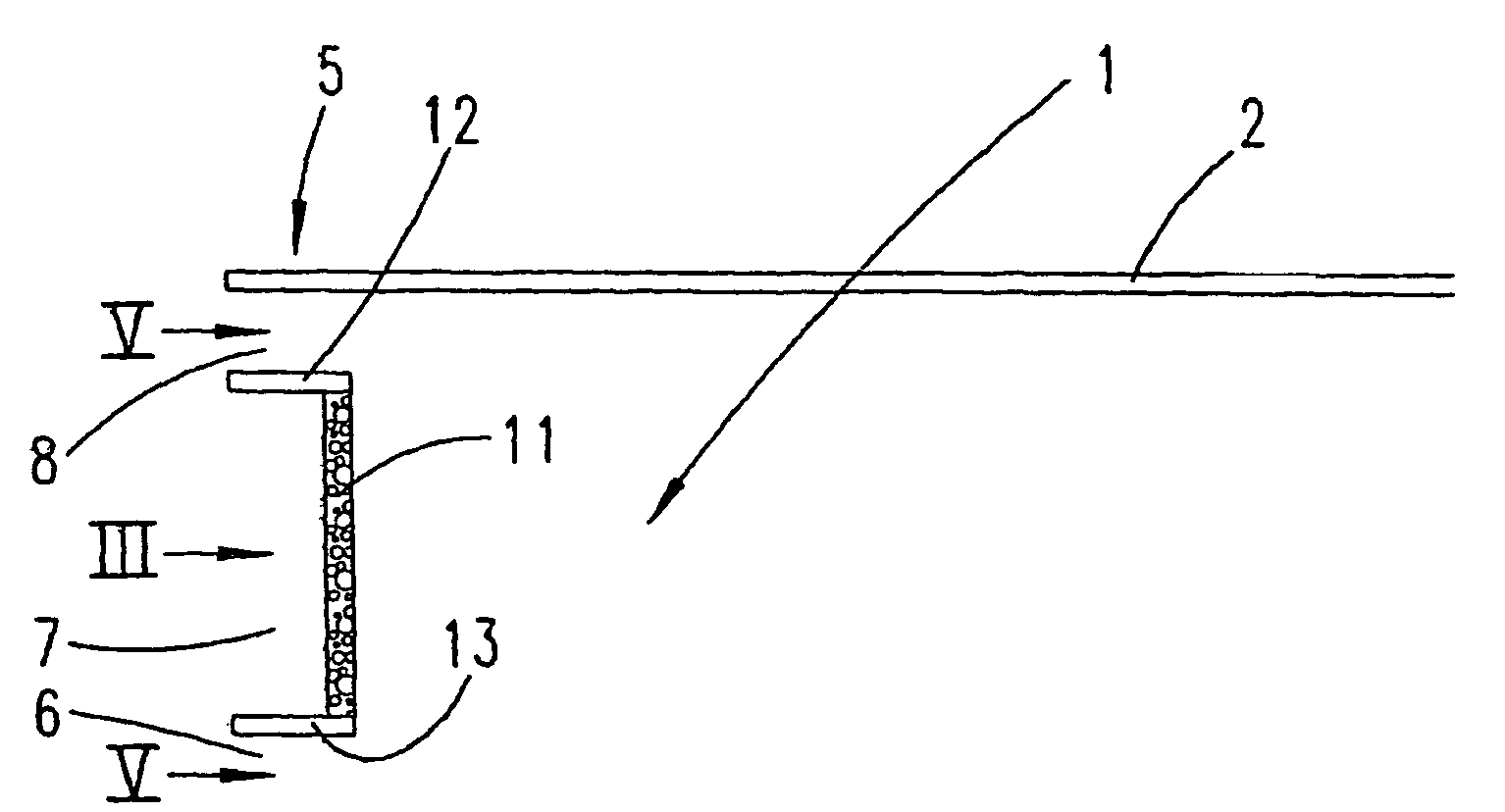
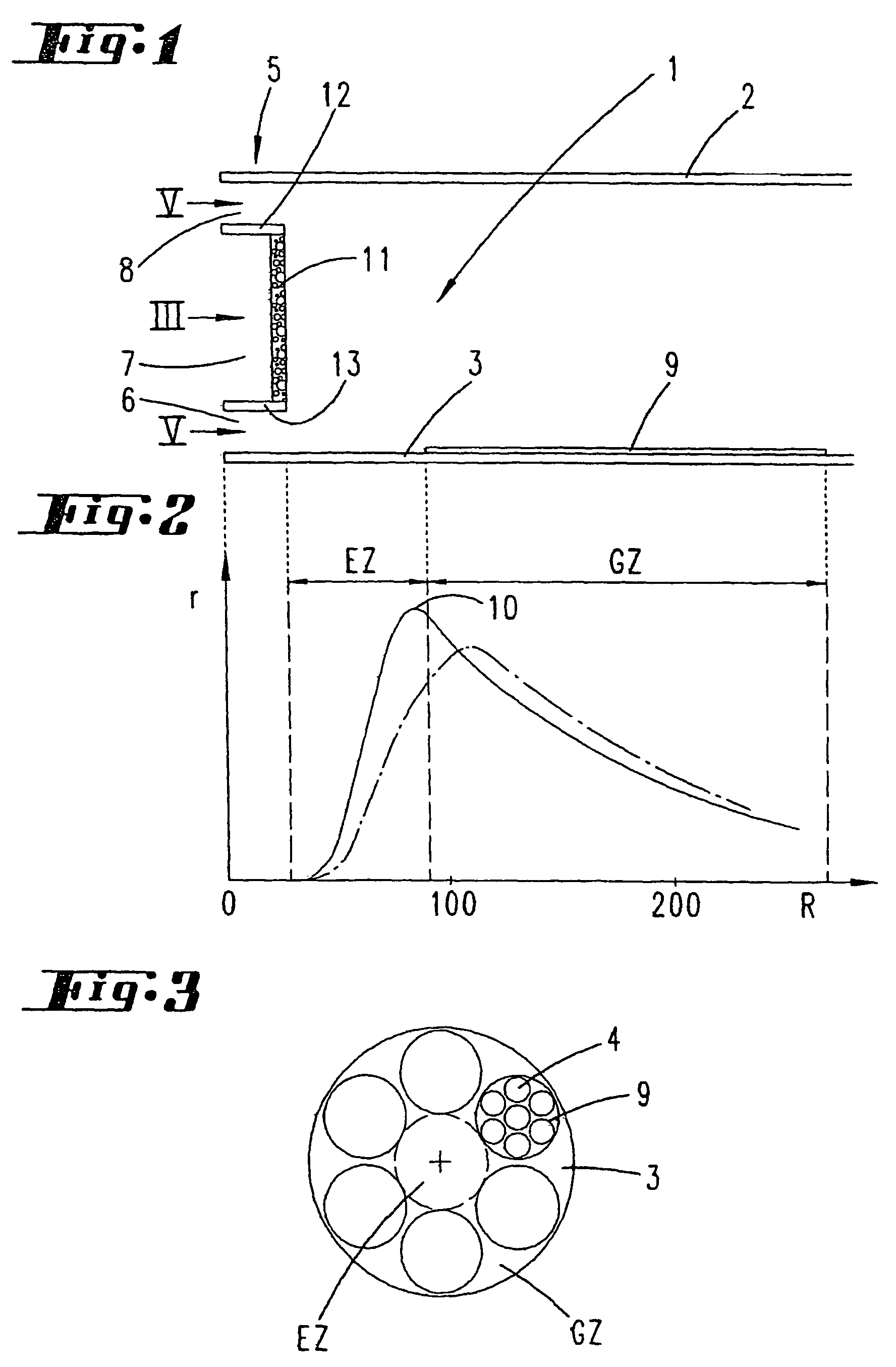
[0016]The exemplary embodiment shows a rotationally symmetrical reactor, in which the gases are introduced at the center and in which the gases are carried away in the region of the periphery. However, the invention also relates to those reactors which have the form of a tube, in which the gas is introduced at one end and the gas is discharged at the other end.

[0017]A significant component is a gas inlet member 5. This is located where the gas is introduced into the process chamber, that is to say at the center in the case of a process chamber 1 of a circular-symmetrical shape. The gas inlet member 5 has three gas inlet zones 6, 7, 8, disposed vertically one above the other. The three gas inlet zones are located between the ceiling 2 and the floor 3 of the process chamber 1.

[0018]In the exemplary embodiment, the floor 3 is actively heated by suitable means. The ceiling 2 is indirectly heated by the heated floor 3 by means of radiation and heat conduction. The heat for heating the fl...


PUM

PropertyMeasurementUnit
concentrationaaaaaaaaaa
sizeaaaaaaaaaa
sizesaaaaaaaaaa

Abstract

The invention relates to a device for depositing especially crystalline layers on at least one especially crystalline substrate in a process chamber comprising a top and a vertically opposing heated bottom for receiving the substrates. A gas-admittance body forming vertically superimposed gas-admittance regions is used to separately introduce at least one first and one second gaseous starting material, said starting materials flowing through the process chamber with a carrier gas in the horizontal direction. The gas flow homogenises in an admittance region directly adjacent to the gas-admittance body, and the starting materials are at least partially decomposed, forming decomposition products which are deposited on the substrates in a growth region adjacent to the admittance region, under continuous depletion of the gas flow. An additional gas-admittance region of the gas-admittance body is essential for one of the two starting materials, in order to reduce the horizontal extension of the admittance region.

Description

CROSS-REFERENCE TO RELATED APPLICATIONS[0001]The present application is a continuation of pending International patent application PCT / EP2005 / 050765 filed on Feb. 23, 2005 which designates the United States and claims priority from German patent application 10 2004 009 130.7 filed on Feb. 25, 2004, the content of which is incorporated herein by reference.FIELD OF THE INVENTION[0002]The invention relates to a device for depositing in particular crystalline layers on one or more in particular crystalline substrates in a process chamber, which has a ceiling and a heated floor, vertically opposite the ceiling, for receiving the substrates, with a gas inlet member, which forms gas inlet zones disposed vertically one above the other for introducing at least a first and a second gaseous starting material separately from one another, which starting materials flow in a horizontal direction together with a carrier gas through the process chamber, the stream of gas being homogenized and the st...

Claims


Application Information

Patent Timeline
Patent Type & Authority Patents(United States)
IPC IPC(8): C30B21/02C23C16/44C23C16/455C30B25/14C30B29/40
CPCC23C16/45568C30B29/40C30B25/14C23C16/00C23C16/455
Inventor DAUELSBERG, MARTINCONOR, MARTINSTRAUCH, GERHARD KARLKAEPPELER, JOHANNES
Owner AIXTRON AG
Why Eureka
Try Eureka