Eureka AIR delivers breakthrough ideas for toughest innovation challenges, trusted by R&D personnel around the world.

Self-ballasted fluorescent lamp and lighting apparatus

a fluorescent lamp and fluorescent lamp technology, applied in the direction of lighting and heating apparatus, discharge tube luminescnet screens, gas-filled discharge tubes, etc., can solve the problems of large light incident on the cover proportionally larger, difficult to bring, and block a large proportion of light distribution to the side, so as to improve the optical output

Inactive Publication Date: 2009-12-01
TOSHIBA LIGHTING & TECH CORP
View PDF13 Cites 1 Cited by
  • Summary
  • Abstract
  • Description
  • Claims
  • Application Information

AI Technical Summary

Benefits of technology

[0006]In order to solve the above problems, an object of the present invention is to provide a self-ballasted fluorescent lamp that is able to have an appearance and light distribution characteristics similar to those of an electric light bulb for general illumination; that improves the optical output; and that is more readily applicable to a lighting fixture that uses an electric light bulb for general illumination, such as an incandescent lamp. Another object of the invention is to provide a lighting apparatus having such a self-ballasted fluorescent lamp.
[0011]If the outer tube diameter of the bulb is less than 3 mm, it not only results in an increased starting voltage and reduced luminance efficiency, but also makes production of the bulb difficult. On the other hand, an outer diameter greater than 8 mm makes it difficult to reduce the maximum outer diameter of the cover.
[0015]A self-ballasted fluorescent lamp according to another embodiment of the present invention has a bottom end and a top end that are respectively located at two lengthwise ends of the self-ballasted fluorescent lamp. The self-ballasted fluorescent lamp includes a luminous tube; a globe encasing the luminous tube; a lighting device for lighting the luminous tube; and a cover housing the lighting device. The luminous tube includes a bulb that has a pair of electrode-side end portions and an outer diameter ranging from 3 to 8 mm. The luminous tube is formed in a bent shape so that the electrode-side end portions of the bulb are located at one end in the height direction of the luminous tube, i.e. the bottom end of the luminous tube, and that the maximum width of the luminous tube, i.e. the maximum dimension in a direction intersecting the height, is limited to not greater than 30 mm. A base is attached to the bottom end of the cover, and the luminous tube and the globe are provided at the other end, i.e. the top end, of the cover. The cover is formed so that the proportion of the distance by which the cover extends from the base to the lamp length excluding the base ranges from 0 to 25% and that the maximum outer diameter of the cover ranges from 0.48 to 0.73 times the maximum outer diameter of the globe. As a result of the configuration described above, the self-ballasted fluorescent lamp is able to have an appearance and light distribution characteristics similar to those of an electric light bulb for general illumination and is more readily applicable to a lighting fixture that uses an electric light bulb for general illumination.
[0024]A self-ballasted fluorescent lamp according to the present invention may have a luminous tube that has one or more bent-shaped bulbs with a plurality of bulb end portions that are located at the bottom end of the luminous tube and that surround the central part of the luminous tube; and may include a holder having a protruding portion, a bulb fitting portion, and a hole. The protruding portion of the holder is adapted to be inserted into the space that is at the center of the bottom end of the luminous tube and surrounded by the bulb end portions. The bulb fitting portion of the holder is provided at the outer wall of the protruding portion so as to face the inward-facing sides of the bulb end portions, which face towards the center of the luminous tube. The bulb fitting portion is adapted to be bonded and thereby fixed to the inward-facing sides of the bulb end portions by means of a bonding agent. The hole of the holder enables the bonding agent to be injected therethrough from the interior of the protruding portion onto the bulb fitting portion. The aforementioned base is provided at the bottom end of the holder. The configuration described above enables the use of the light emitted from the outer surface of the bulb end portions of the luminous tube to radiate to the outside, resulting in an improved optical output.
[0029]A self-ballasted fluorescent lamp according to the present invention may have a holder that is provided with a contact portion with which the end faces of the bulb end portions come into contact and are fixed thereto by means of a bonding agent. The aforementioned base is provided at the bottom end of the holder. The configuration described above enables the use of the light emitted from the outer surface of the bulb end portions of the luminous tube to radiate to the outside, resulting in an improved optical output.

Problems solved by technology

Such a large cover not only makes it difficult to bring the appearance of the self-ballasted fluorescent lamp sufficiently close to that of an electric light bulb for general illumination but also makes the light incident upon the cover proportionally larger due to the large outer diameter of the cover, thereby blocking a large proportion of light distribution to the side where the base is provided.
As a result, during the time the luminous tube is lit, light distribution characteristics are not sufficiently similar to those of an electric light bulb for general illumination.
Furthermore, as the end portions of the bulbs of the luminous tube are respectively bonded and thereby secured in the bulb insertion holes of the holder by means of a bonding agent, the light emitted from the end portions of the bulbs, which are fitted in the holder, shines into the holder and cannot be radiated to the outside.
These drawbacks of the conventional self-ballasted fluorescent lamp lessens its applicability to a lighting fixture that uses an electric light bulb for general illumination.

Method used


Image

  • Self-ballasted fluorescent lamp and lighting apparatus
  • Self-ballasted fluorescent lamp and lighting apparatus
  • Self-ballasted fluorescent lamp and lighting apparatus

Examples


Embodiment Construction

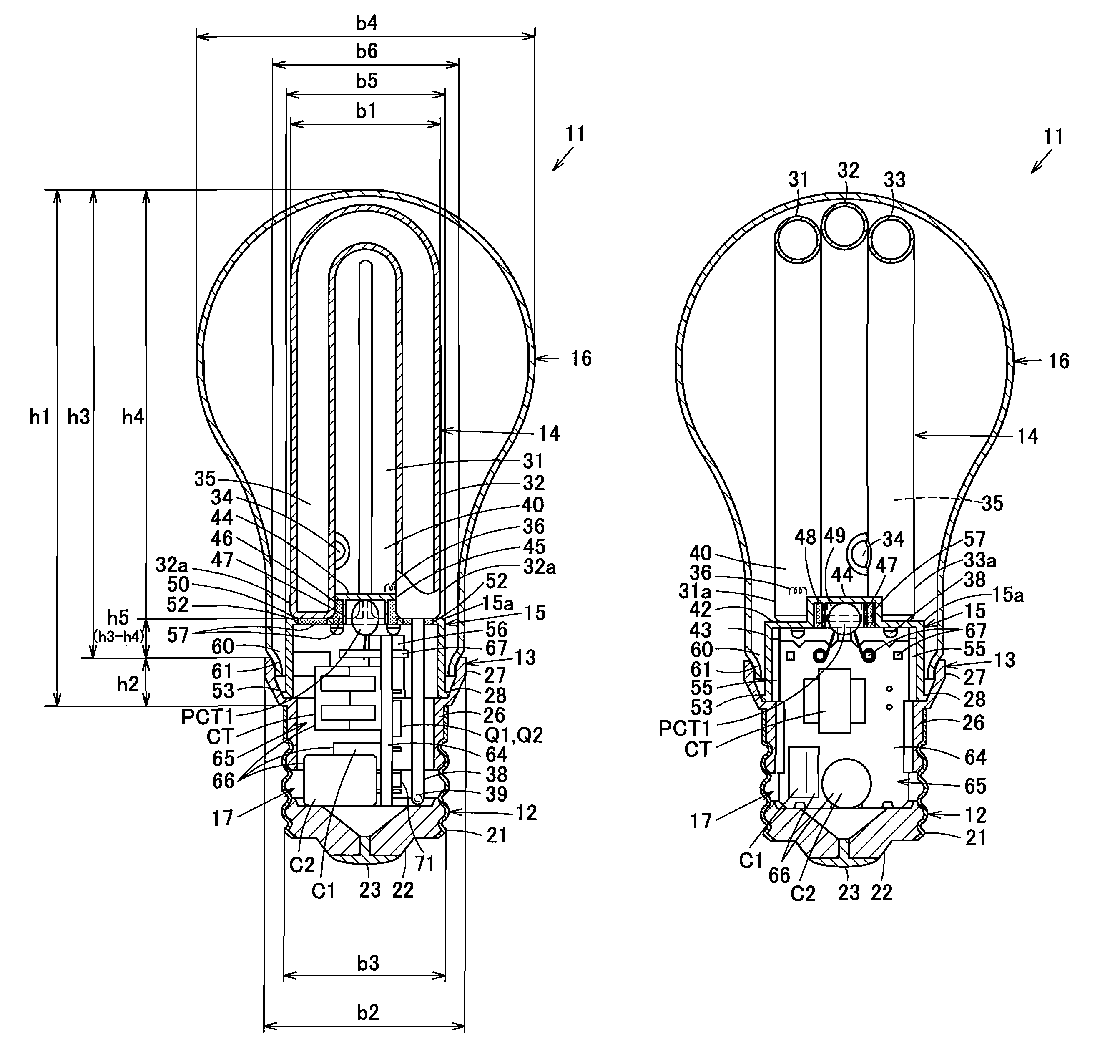
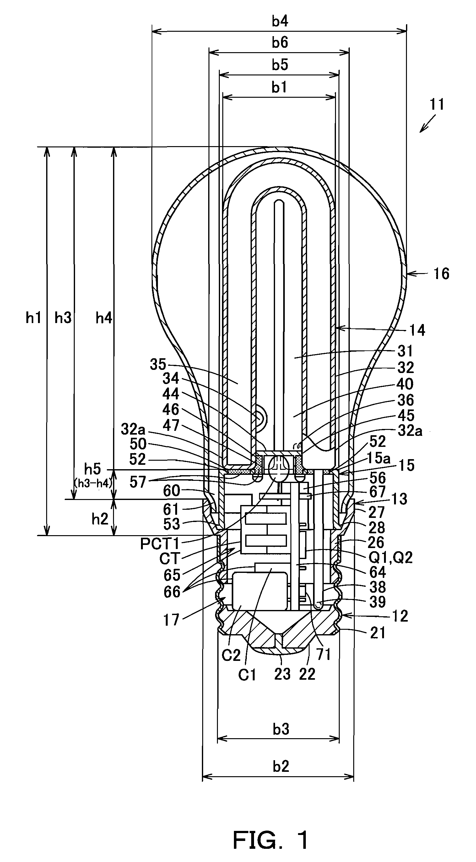
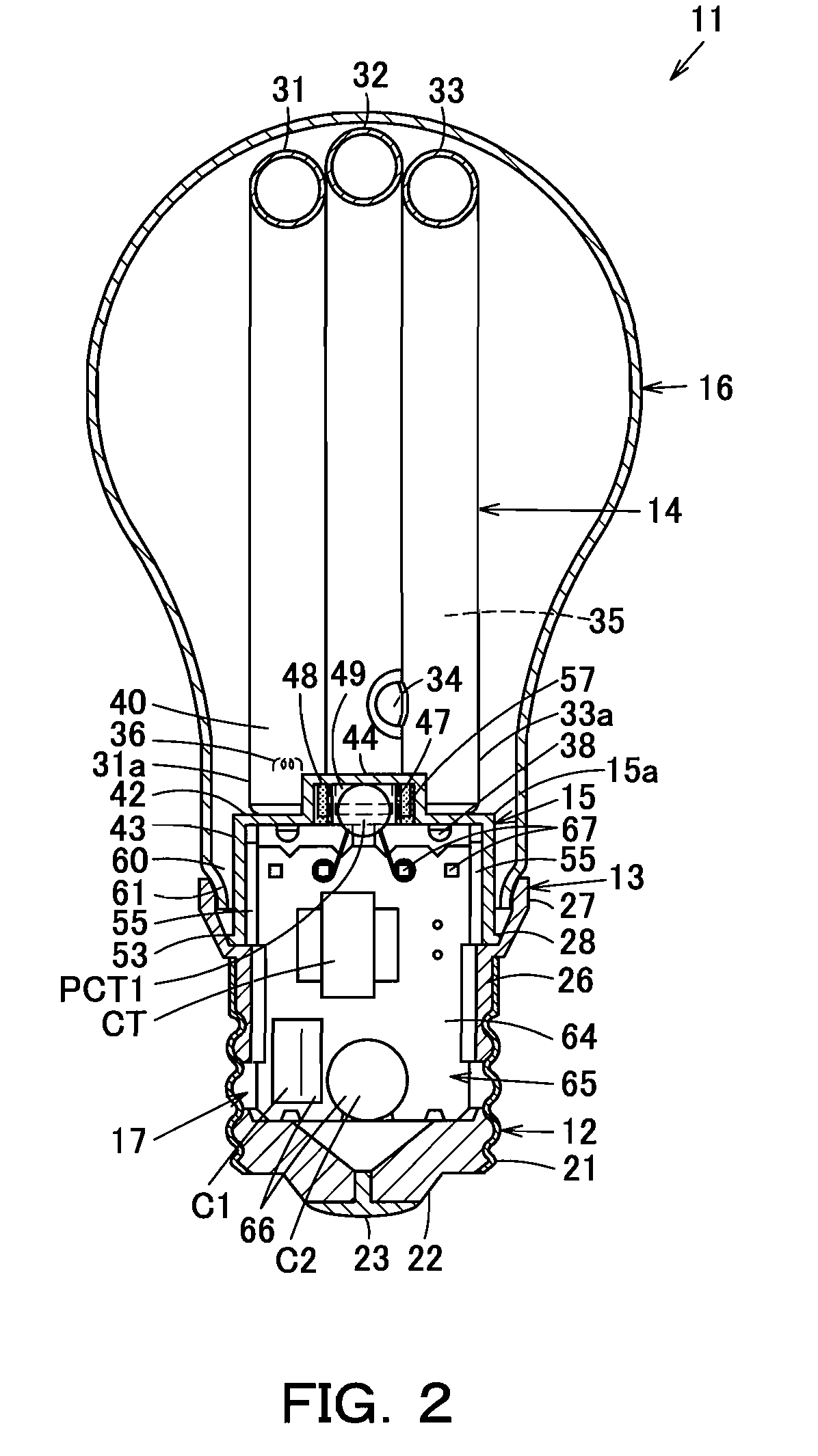
[0053]The following table provides a key to the reference numerals and elements depicted in the drawings.

[0054]11 self-ballasted fluorescent lamp

[0055]12 base

[0056]13 cover

[0057]14 luminous tube

[0058]15 holder

[0059]16 globe

[0060]17 lighting device

[0061]31,32,33,91 bulb

[0062]31a,32a,33a, bulb end portion

[0063]44 protruding portion

[0064]40 electrode-side end portion

[0065]45 concave portion as bulb fitting portion

[0066]46 hole

[0067]47 wall portion

[0068]50 contact portion

[0069]51 recessed portion as positioning portion

[0070]52 insertion hole

[0071]57 bonding agent

[0072]81 lighting apparatus

[0073]82 lighting apparatus body

[0074]83 socket

[0075]Features of the self-ballasted fluorescent lamp according to the present invention may be further characterized as follows.

[0076]According to one embodiment of the present invention, the luminous tube having a bulb with an outer diameter ranging from 3 to 8 mm is formed so that the maximum width of the luminous tube is limited to not greater than 30 ...


PUM


Abstract

A self-ballasted fluorescent lamp includes a luminous tube that is formed in a bent shape with a pair of electrode-side end portions located at a the bottom end of the luminous tube. A cover houses a lighting device for lighting the luminous tube. A base is attached to the bottom end of the cover, and the luminous tube is supported at the top end, of the lamp. The outer diameter of a bulb of the luminous tube 14 ranges from 3 to 8 mm, and the maximum width of the luminous tube, is not greater than 30 mm. The cover is formed so that the proportion of the distance by which the cover extends from the base to the lamp length excluding the base ranges from 0 to 25%, and so that the maximum outer diameter of the cover ranges from 1.0 to 1.5 times the outer diameter of the base.

Description

CROSS-REFERENCE TO RELATED APPLICATIONS[0001]This application is the national phase under 35 U.S.C. §371 of International Application PCT / JP2006 / 305920, filed Mar. 24, 2006, which claims the benefit of Japanese Patent Application Nos. 2005-087002 filed Mar. 24, 2005, 2005-276930 filed Sep. 22, 2005 and 2005-276931 filed Sep. 22, 2005, all of which are incorporated by reference herein. The International Application was published in Japanese on Sep. 28, 2006 as WO 2006 / 101190 A1 under PCT Article 21(2).FIELD OF THE INVENTION[0002]The present invention relates to a self-ballasted fluorescent lamp with appearance and light distribution characteristics similar to those of an electric light bulb for general illumination. The present invention further relates to a lighting apparatus provided with the self-ballasted fluorescent lamp.BACKGROUND OF THE INVENTION[0003]A conventional self-ballasted fluorescent lamp is disclosed, for example, by Japanese Laid-Open Patent Publication No. 2000-213...

Claims


Application Information

Patent Timeline
Patent Type & Authority Patents(United States)
IPC IPC(8): H01J1/62H01J63/04F21Y103/37
CPCH05B41/2988H01J61/30
Inventor IKADA, KUNIHIKOKUBOTA, HIROSHITANAKA, TOSHIYA
Owner TOSHIBA LIGHTING & TECH CORP
Why Eureka
Eureka Blog
Learn More