Bicycle wheel securing structure

a technology for bicycle wheels and securing structures, which is applied in the direction of cycle equipment, release mechanisms, steering devices, etc., can solve the problems of difficult for some individuals to tighten such a knob, other bicycle parts such as bicycle wheels need to be loosened and removed, etc., and achieves the effect of tight connection and easy tightening

Active Publication Date: 2009-12-08
SHIMANO INC
View PDF9 Cites 18 Cited by
  • Summary
  • Abstract
  • Description
  • Claims
  • Application Information

AI Technical Summary

Benefits of technology

[0009]One object of the present invention is to provide a bicycle wheel securing structure, which provides a tight connection, yet is relatively easy to tighten.
[0010]Another object of the present invention is to provide a bicycle wheel securing structure, which is relatively simple and inexpensive to manufacture and / or assemble.

Problems solved by technology

However, while certain bicycle parts are designed to be permanently attached to the bicycle, other bicycle parts such as bicycle wheels need to be loosened and removed relatively often.
However, it can be difficult for some individuals to tighten such a knob.
In fact, individuals that have difficulty tightening the knob to the desired tightness level may even use a tool in order to achieve the desired level of tightness, which is inconvenient.

Method used


Image

  • Bicycle wheel securing structure
  • Bicycle wheel securing structure
  • Bicycle wheel securing structure

Examples


Embodiment Construction

[0030]A selected embodiment of the present invention will now be explained with reference to the drawings. It will be apparent to those skilled in the art from this disclosure that the following descriptions of the embodiment of the present invention are provided for illustration only and not for the purpose of limiting the invention as defined by the appended claims and their equivalents.

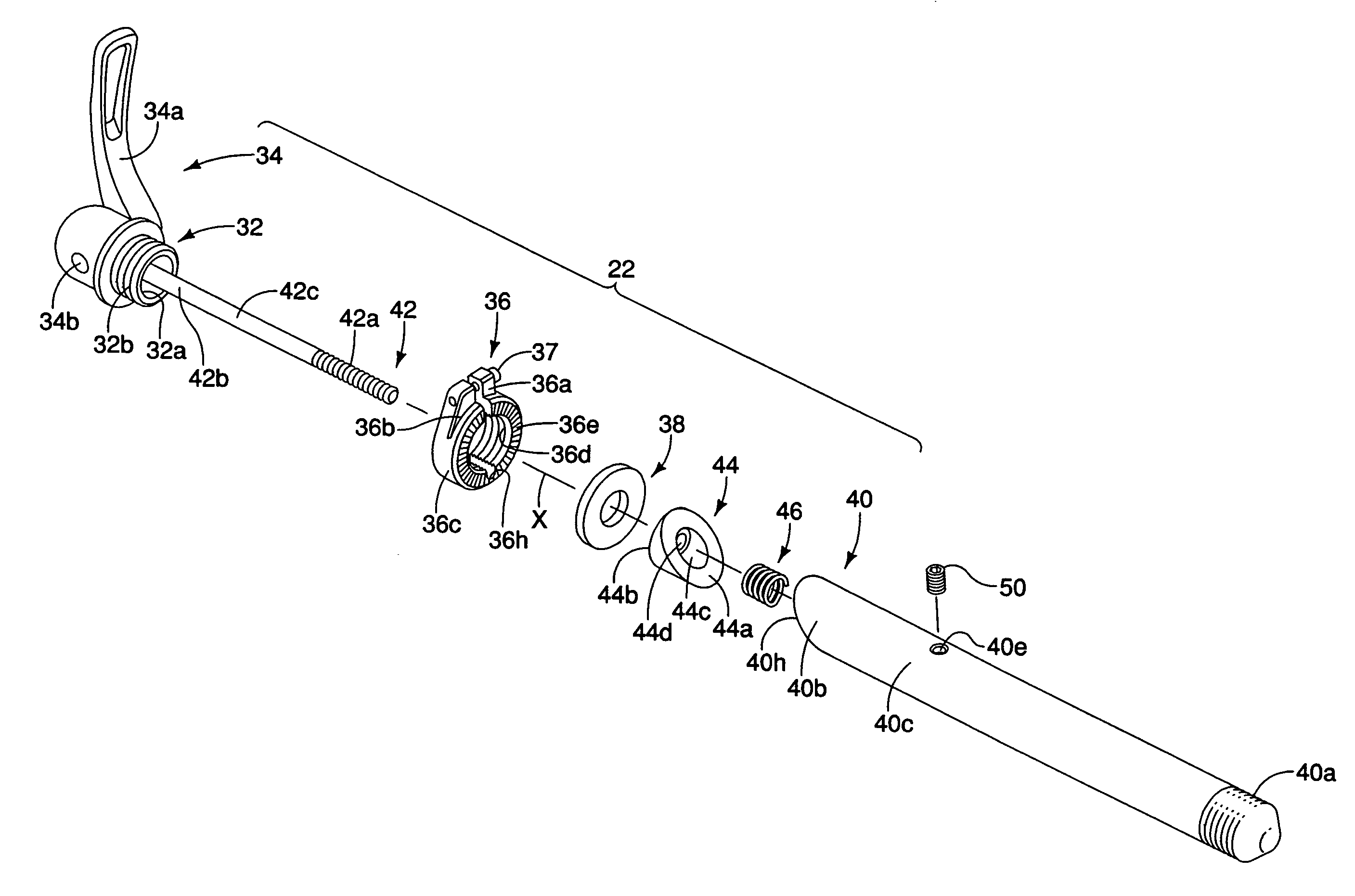
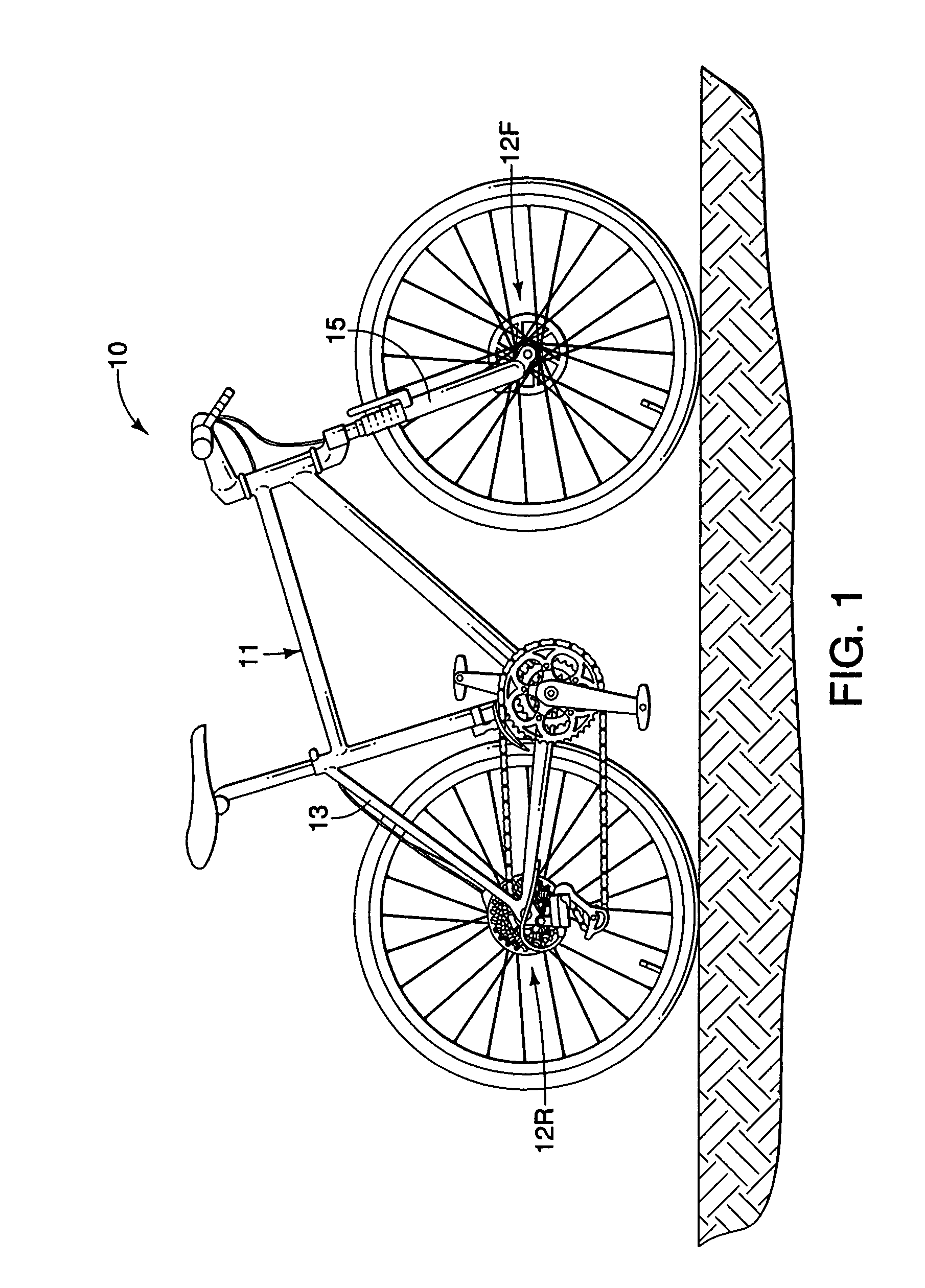
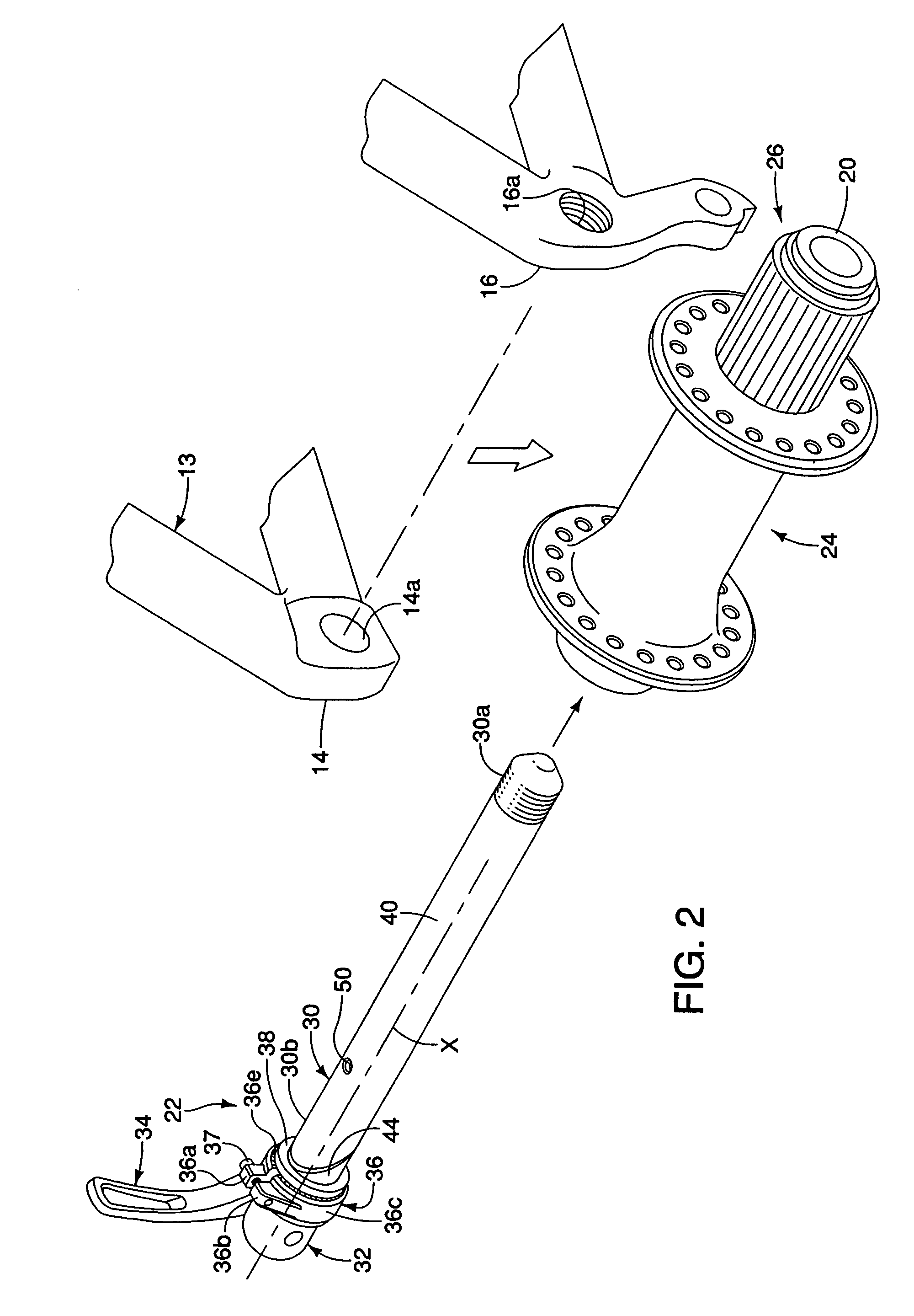
[0031]Referring initially to FIG. 1, a bicycle 10 is illustrated, which has a rear bicycle hub 12R and a front bicycle hub 12F coupled thereto in accordance with one preferred embodiment of the present invention. The rear hub 12R is attached the frame 11 of the bicycle 10 using a wheel securing axle 22 in accordance with the present invention. Specifically, the frame 11 includes a rear fork or triangle 13 with a pair of hub mounting flanges 14 and 16 formed at the free ends thereof. Preferably, one end of the wheel securing axle 22 is directly threadedly attached to the mounting flange 16, while th...


PUM


Abstract

A bicycle wheel securing structure includes a shaft member, a head member, a lever member and a radial expansion structure. The shaft member has first and second end portions. The head member is coupled at the second end portion. The lever member is operatively mounted to move the shaft member in an axial direction relative to the head member in response to movement of the lever member. The radial expansion structure is disposed at the second end portion and includes an expansion member and the second end portion of the shaft member. The expansion member has a first inclined surface and the second end portion of the shaft member has a second inclined surface that cooperates with the first inclined surface to radially expand an outer diameter of the radial expansion structure in response to movement of the lever member from a release position to an attachment position.

Description

BACKGROUND OF THE INVENTION[0001]1. Field of the Invention[0002]This invention generally relates to a bicycle wheel securing structure. More specifically, the present invention relates to a bicycle wheel securing structure, which provides a radial securing force in addition to an axial securing force.[0003]2. Background Information[0004]Bicycling is becoming an increasingly more popular form of recreation as well as a means of transportation. Moreover, bicycling has become a very popular competitive sport for both amateurs and professionals. Whether the bicycle is used for recreation, transportation or competition, the bicycle industry is constantly improving the various components of the bicycle. One component that has been extensively redesigned is the bicycle wheel securing mechanism.[0005]In the past various bicycle parts have been attached using nut and bolt arrangements. However, while certain bicycle parts are designed to be permanently attached to the bicycle, other bicycle ...

Claims


Application Information

Patent Timeline
Patent Type & Authority Patents(United States)
IPC IPC(8): B62M1/02B62M1/36B62J99/00
CPCB62K25/02B62K2206/00B60B27/026
Inventor HARA, NOBUKATSU
Owner SHIMANO INC
Why Eureka
Try Eureka