Mechanical strap tensioner for multi-strand tensioning

a multi-strand tensioner and mechanical technology, applied in the direction of gearing control, gearing elements, gearing, etc., can solve the problems of inoperable engine, fluctuations in the tension of any given portion of the chain, and increase the slack or wear conditions

Inactive Publication Date: 2009-12-08
BORGWARNER INC
View PDF13 Cites 11 Cited by
  • Summary
  • Abstract
  • Description
  • Claims
  • Application Information

AI Technical Summary

Benefits of technology

[0017]The second end of each tensioning arm is pivotally connected to the other tensioning arm by an adjusting arm. The adjusting arm includes two pairs of rigid elongated straps that adjustably overlap with each other substantially in the middle of the length of the adjusting arm. The overlapping ends of the first pair of elongated straps terminate in hook shapes to provide a seat for a first end of a lengthening coil spring. The overlapping ends of the second pair of elongated straps also terminate in hook shapes that insert through slots formed in each of the first pair of elongated straps. The hook shaped ends of the second pair of straps provide a seat for a second end of the lengthening coil spring. Each strap of the first pair of elongated straps contains a rack of teeth that operatively meshes with a rack of teeth on each strap of the second pair of elongated straps. The lengthening coil spring urges the overlap of both pair of elongated straps so that the adjusting arm continues to shorten in response to increasing slack or wear conditions experienced by the chain. The meshing teeth provide a “no-return” feature by engaging the teeth in only one direction.

Problems solved by technology

Prevention of such slippage is particularly important in the case of a chain driven camshaft in an internal combustion engine because the jumping of teeth will throw off the camshaft timing, possibly causing damage to the engine or rendering it inoperative.
However, in the harsh environment of the internal combustion engine, numerous factors cause fluctuations in the tension of any given portion of the chain.
For instance, extreme temperature fluctuations and differences in the relative rates of thermal expansion coefficients among the various parts of the engine can cause the chain tension to vary between excessively high or very low levels.
During prolonged use, wear to the components of the power transmission system can cause a steady decrease in chain tension.
In addition, camshaft and crankshaft induced torsional vibrations cause considerable variations in chain tensions.
For example, the reverse rotation of an engine, occurring during stopping of the engine or in failed attempts at starting the engine, can also cause significant fluctuations in chain tension.
In this way, the tensioner achieves the no-return function, i.e., movements of the plunger are easy in one direction (outward and away from the housing) but difficult in the reverse direction.

Method used


Image

  • Mechanical strap tensioner for multi-strand tensioning
  • Mechanical strap tensioner for multi-strand tensioning
  • Mechanical strap tensioner for multi-strand tensioning

Examples


Embodiment Construction

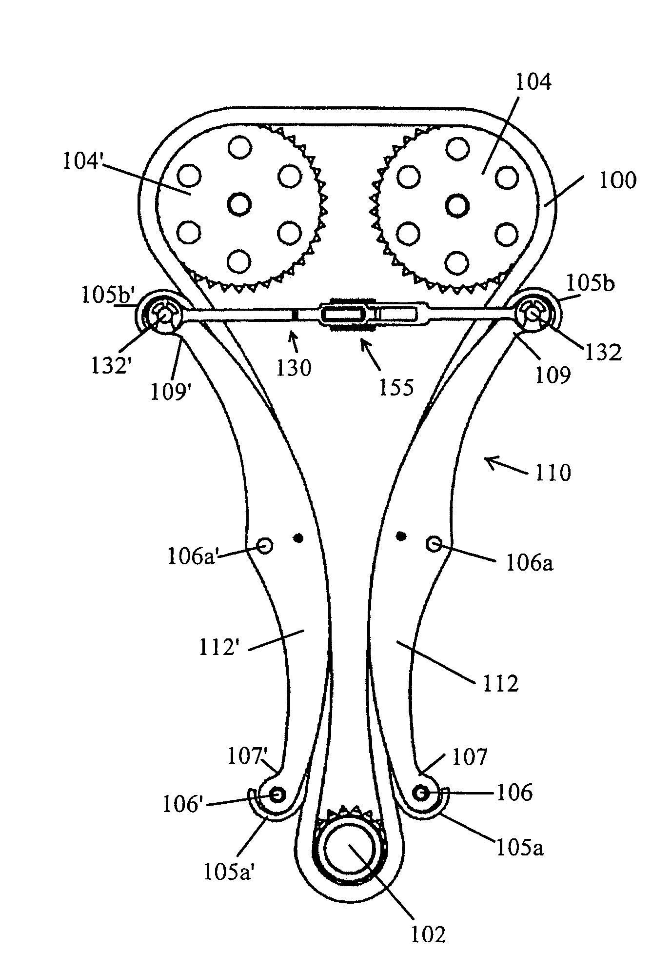
[0027]Referring to FIG. 5, the tensioner 110 of the present invention is operatively engaged with a closed loop power transmission system of an internal combustion engine. The power transmission system contains a driving sprocket 102 and at least one driven sprocket 104, 104′. Power from the engine's drive shaft is transmitted from the driving sprocket 102 to the driven sprockets by means of a chain 100 or drive belt. Most commonly used with internal combustion engines are chain drives. Proper tension must be applied to the chain 100 at all times in order to prevent the jumping of the sprocket teeth by the chain during slackening of any portion of the chain during operation or as a result of increasing wear of the components over time.

[0028]The tensioner 110 includes a tensioning arm 112 that is operatively engaged with the outer surface of one of the strands of chain between the driving sprocket 102 and one of the driven sprockets 104. The second tensioning arm 112′ of tensioner 11...


PUM


Abstract

A tensioner for a closed loop power transmission system for an internal combustion engine having a drive shaft terminating in a sprocket and at least one camshaft, each terminating in a sprocket, with a single continuous chain wrapping around all of the sprockets. The tensioner contains a pair of elongated tensioning arms, each one in slidable contact with one of the two strands of chain that traverses between the driving sprocket and the driven sprocket(s). Each tensioning arm contains a wear face that remains in constant slidable contact with the strand of chain to which it is adjacent. An adjusting arm connects one of the ends of the tensioning arms. The adjusting arm has a ratchet means that adjusts for the backlash in the system and takes up any slack in the chain.

Description

FIELD OF THE INVENTION[0001]The invention pertains to the field of chain tensioners. More particularly, the invention pertains to a tensioner for two strands of chain that contains a ratcheting device.DESCRIPTION OF RELATED ART[0002]A tensioning device, such as a hydraulic tensioner, is used as a control device for a power transmission chain, or similar power transmission device, as the chain travels between a plurality of sprockets that are connected to the operating shafts of an internal combustion engine. In this system, the chain transmits power from a driving shaft to a driven shaft, so that part of the chain is slack and part of the chain is tight. Generally, it is important to impart and maintain a certain degree of tension on the chain to prevent noise, slippage, or the unmeshing of teeth as in the case of a toothed chain. Prevention of such slippage is particularly important in the case of a chain driven camshaft in an internal combustion engine because the jumping of teeth...

Claims


Application Information

Patent Timeline
Patent Type & Authority Patents(United States)
IPC IPC(8): F16H59/00
CPCF16H7/0848F16H2007/0804F16H2007/0874F16H2007/0853F16H2007/0872F16H2007/0806
Inventor MARKLEY, GEORGE L.
Owner BORGWARNER INC
Why Eureka
Try Eureka