Displacement Detecting Device

a technology of displacement detection and detecting device, which is applied in the direction of measurement device, interferometer, instruments, etc., can solve the problems of limited service conditions and limit the mechanical response frequency of the up-down movement of the objective lens, so as to reduce the heat generated during use and ease the service conditions

Active Publication Date: 2013-09-26
DMG MORI SEIKI CO LTD
View PDF4 Cites 11 Cited by
  • Summary
  • Abstract
  • Description
  • Claims
  • Application Information

AI Technical Summary

Benefits of technology

[0016]With the displacement detecting devices of the present invention, since the conventional drive mechanism is not necessary, the heat generated during use can be reduced. Further, since it is not necessary to drive the drive mechanism, there will be no problem of response frequency, and therefore service conditions can be eased.

Problems solved by technology

Thus, due to the structure and mass of the actuator, there is a limitation in mechanical response frequency of the up-down movement of the objective lens.
Further, although detecting points can be narrowed, there is a problem that big error will be raised due to being affected by the influence of foreign matter on the object-to-be-measured and / or the influence of beam-like minute change of the shape of the object-to-be-measured, so that service conditions are limited.

Method used


Image

  • Displacement Detecting Device
  • Displacement Detecting Device
  • Displacement Detecting Device

Examples


first embodiment

1. Displacement Detecting Device

[0051]First, the configuration of a displacement detecting devices 1 according to a first embodiment (referred to as “the present embodiment” hereinafter) of the present invention will be described below with reference to FIGS. 1 to 5.

1-1. Configuration Example of Displacement Detecting Device

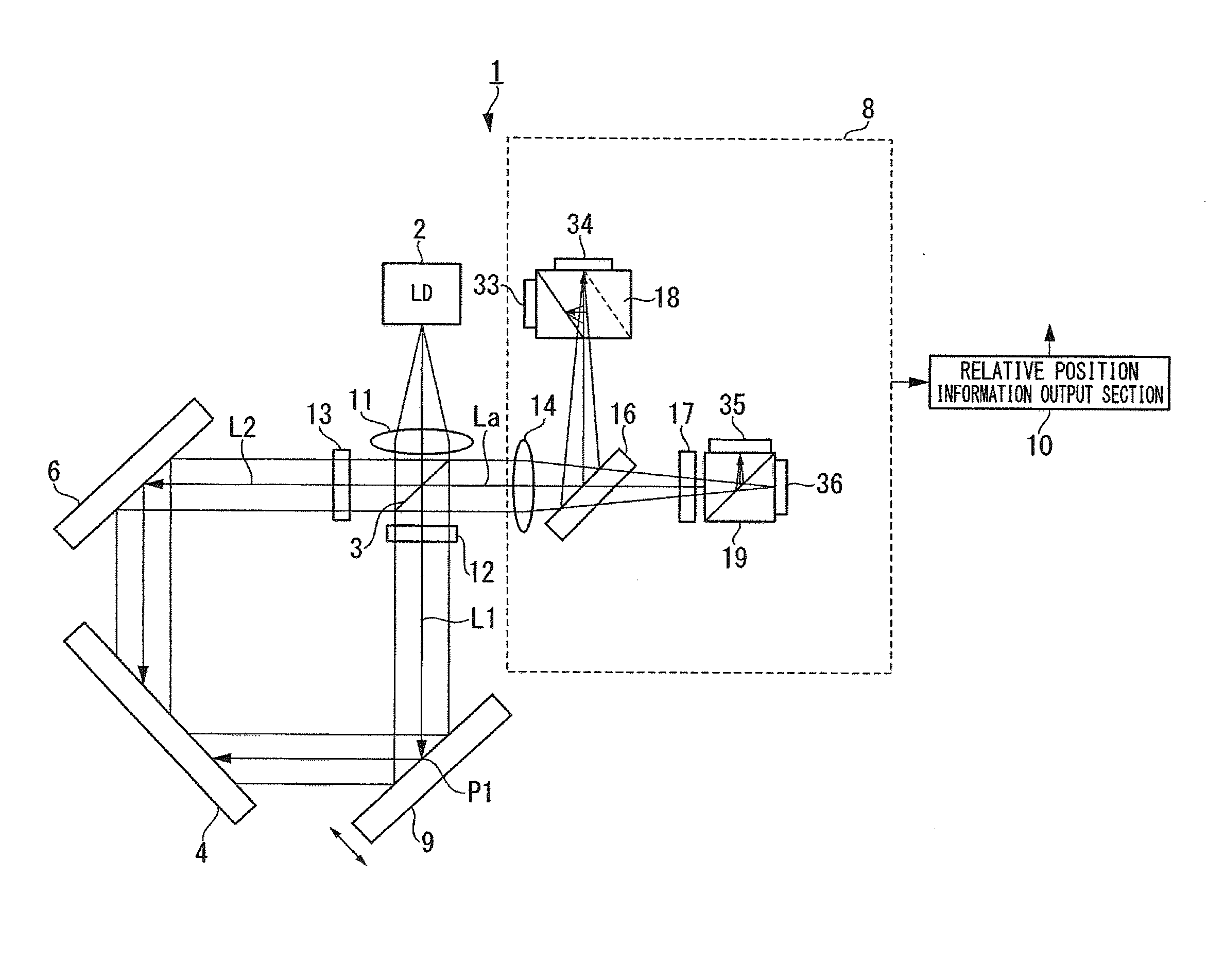
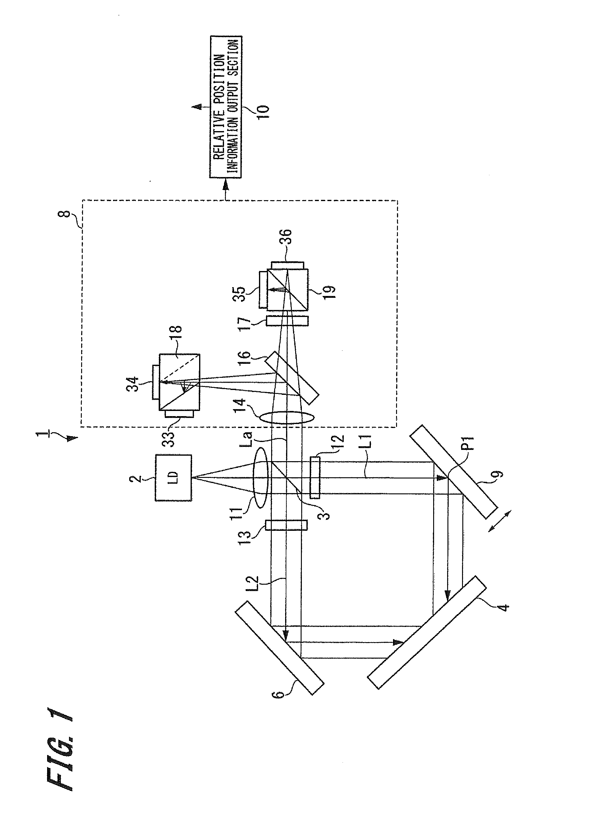
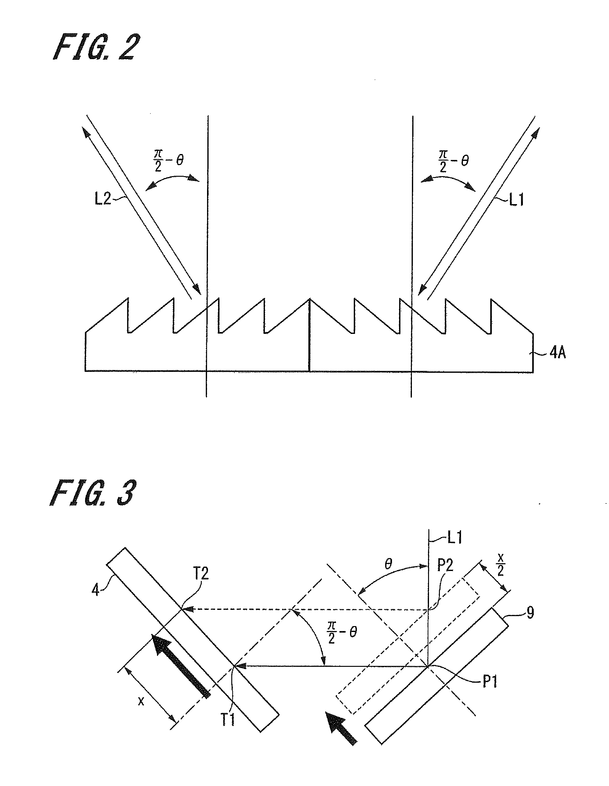
[0052]FIG. 1 is a view schematically showing the configuration of a displacement detecting device 1, FIG. 2 is a side view showing an example of a diffraction grating of the displacement detecting device 1, FIG. 3 is a view for explaining a primary portion of the displacement detecting device 1, and FIG. 4 is a block diagram showing schematic configuration of a relative position information output section of the displacement detecting device 1.

[0053]The displacement detecting device 1 according to the present embodiment is a displacement detecting device capable of detecting vertical displacement of a surface-to-be-measured by using a diffraction grating. As show...

second embodiment

3. Displacement Detecting Device

[0114]Next, a displacement detecting device 101 according to a second embodiment of the present invention will be described below with reference to FIG. 6.

[0115]FIG. 6 is a view schematically showing the configuration of the displacement detecting device 101.

[0116]The displacement detecting device 101 of the second embodiment differs from the displacement detecting device 1 of the first embodiment in that the displacement detecting device 101 is provided with a second mirror 104 to second-diffract the first beam L1 and the second beam L2. Thus, hereinafter, only the second mirror 104 will be described, and components common to those of the displacement detecting device 1 of the first embodiment will be denoted by the same reference numerals and the explanation thereof will be omitted.

[0117]As shown in FIG. 6, in the displacement detecting device 101, the second mirror 104 is disposed so as to face the diffraction grating 4. Further, the first beam L1 ...

third embodiment

4. Displacement Detecting Device

[0121]Next, a displacement detecting device 201 according to a third embodiment of the present invention will be described below with reference to FIG. 7, FIG. 8 and FIG. 9.

[0122]FIG. 7 is a view schematically showing the configuration of the displacement detecting device 201. FIG. 8 is a view showing an example of an irradiation image irradiated onto a light receiving section for absolute value of the displacement detecting device 201, and FIG. 9 is a view showing the characteristic of a signal obtained based on the light amount detected by the light receiving section for absolute value.

[0123]The displacement detecting device 201 of the third embodiment differs from the displacement detecting device 1 of the first embodiment in that in the displacement detecting device 201, a second condensing lens 202 and a third condensing lens 203 are provided and absolute position detection is performed. Thus, hereinafter, only the second condensing lens 202 and ...


PUM


Abstract

A displacement detecting device includes a light source, a beam splitting section, a diffraction grating, a reflecting section, a beam combining section, a light receiving section, and a relative position information output section. The diffraction grating is adapted to diffract a first beam reflected by a surface-to-be-measured of a member-to-be-measured, and cause the diffracted first beam to be incident again on the surface-to-be-measured. The reflecting section is adapted to reflect a second beam split by the beam splitting section to the beam splitting section. The light receiving section is adapted to receive interfering light of the first beam and the second beam. The relative position information output section is adapted to output displacement information of the surface-to-be-measured in the height direction based on intensity of the received interfering light.

Description

CROSS REFERENCES TO RELATED APPLICATIONS[0001]The present invention contains subject matter related to Japanese Patent Application JP 2012-018715 filed in the Japanese Patent Office on Jan. 31, 2012, the entire contents of which being incorporated herein by reference.BACKGROUND OF THE INVENTION[0002]1. Field of the Invention[0003]The present invention relates to a displacement detecting device for detecting displacement of a surface-to-be-measured by a non-contact sensor which uses light emitted from a light source. More particularly, the present invention relates to a technology for detecting vertical displacement of the surface-to-be-measured.[0004]2. Description of the Related Art[0005]Conventionally, a displacement detecting device for measuring displacement and shape of a surface-to-be-measured by light in a non-contact manner is widely used. As a typical example, there is a method in which a laser is irradiated onto the surface-to-be-measured, and change of the position of the...

Claims


Application Information

Patent Timeline
Patent Type & Authority Applications(United States)
IPC IPC(8): G01B9/02
CPCG01B9/02015G01B9/02018G01B9/02081G01B2290/70G01B9/02022G01B9/02G01B11/00
Inventor TAMIYA, HIDEAKI
Owner DMG MORI SEIKI CO LTD
Why Eureka
Try Eureka