Dynamically adjusting operation of one or more sensors of a computer input device

a computer input device and dynamic adjustment technology, applied in computing, instruments, electric digital data processing, etc., can solve the problems of significant draining of battery power, consuming a substantial amount of electrical energy for the image components necessary for optical tracking, and light sources (as well as processing electronics) showing a significant drain on battery power, so as to increase the activation rate and reduce the activation rate.

Inactive Publication Date: 2009-12-08
MICROSOFT TECH LICENSING LLC
View PDF8 Cites 29 Cited by
  • Summary
  • Abstract
  • Description
  • Claims
  • Application Information

AI Technical Summary

Problems solved by technology

An inherent challenge with wireless devices such as computer mice is power management.
Although a significant advancement, the imaging components necessary for optical tracking consume a substantial amount of power.
When activated at a high rate for prolonged periods, the light source (as well as the processing electronics) exhibit a significant drain on battery power.

Method used


Image

  • Dynamically adjusting operation of one or more sensors of a computer input device
  • Dynamically adjusting operation of one or more sensors of a computer input device
  • Dynamically adjusting operation of one or more sensors of a computer input device

Examples


Embodiment Construction

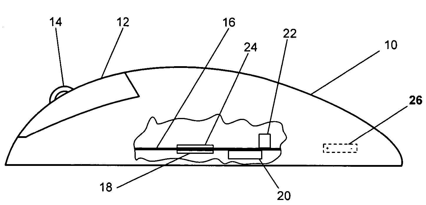
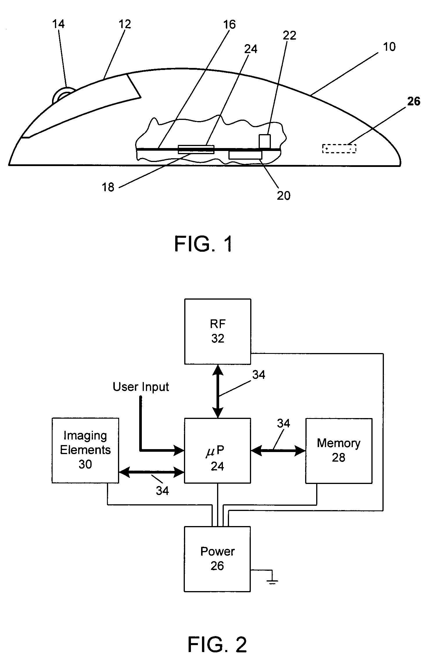
[0024]The present invention permits improved power management in a wireless computer input device. Although the invention is described using a wireless, optically-tracking computer mouse as an example, the invention may also be implemented in other wireless devices using optical tracking. As but one example, the invention could also be implemented in a wireless trackball. In an optically tracking trackball, the tracked surface may be the outer surface of a ball which is rotatably captured within a housing. An imager within the housing detects displacement of the ball surface (relative to the imager) as a user rotates the ball. As another example, the invention could be implemented in an optical scroll wheel. In such scroll wheels, a rotating wheel is imaged, and the speed (and direction) of rotation relative to the imager determined. The invention may also be implemented in a computer input device having other types of sensors (e.g., pressure sensors, capacitive sensors, etc.).

[0025...


PUM


Abstract

A computer input device controller dynamically adjusts the rate at which an illumination source is activated, and may also adjust the rate at which other optical tracking system components are activated. As the velocity of optical tracking system movement relative to a tracked surface increases, the controller increases the activation rate(s). As the velocity of relative movement decreases, the controller decreases the activation rate(s). Future displacements of a tracking system relative to a tracked surface are also estimated. In particular, relative tracking system / tracked surface velocity is calculated based on a series of images. Relative displacement is then estimated based on the calculated velocity.

Description

FIELD OF THE INVENTION[0001]This invention relates to power management in electronic devices. In particular, the present invention relates to power management in a computer input device.BACKGROUND OF THE INVENTION[0002]Wireless communication over relatively short distances is a common and increasingly important feature of electronic devices. In some cases, for example, an electronic device or other appliance is controlled by another electronic device which must communicate instructions to the controlled device (and perhaps receive information from the controlled device). Examples include computer input devices such as mice. Among other advantages, wirelessly transmitting data and / or control signals between a computer and a mouse can dramatically increase user convenience and reduce clutter from multiple connecting cables.[0003]An inherent challenge with wireless devices such as computer mice is power management. Wireless devices are usually battery powered. To prolong battery life, ...

Claims


Application Information

Patent Timeline
Patent Type & Authority Patents(United States)
IPC IPC(8): G09G5/08
CPCG06F3/0383G06F3/0317
Inventor CASEBOLT, MARK W.LEE, MARK R.POPE, JEREMIAH M.MARSHALL, JAMES C.
Owner MICROSOFT TECH LICENSING LLC
Why Eureka
Try Eureka