Electronic circuit breaker

a circuit breaker and electronic technology, applied in the field of electronic circuit breakers, can solve the problems of circuit breakers that are not entirely reliable, thermal circuit breakers that have a high tripping time, and have a large unreliable tripping speed, and achieve the effect of more reliable and higher mtb

Inactive Publication Date: 2009-12-08
ABB (SCHWEIZ) AG
View PDF37 Cites 22 Cited by
  • Summary
  • Abstract
  • Description
  • Claims
  • Application Information

AI Technical Summary

Benefits of technology

[0010]In particular, a purpose of the present invention is to provide a reliable electronic circuit breaker that has characteristics of high durability and very short tripping times, presents a galvanic insulation between the input and the output when it is in the opening condition, and enables limitation of peak current.
[0011]A further purpose of the present invention is to provide a circuit breaker device that can be programmed.
[0018]The circuit breaker according to the invention presents numerous advantages as compared to circuit breakers of the prior art. The circuit breaker of the present invention is more reliable, with a higher MTBF, because a relay that switches in the absence of a voltage across its contacts has a longer life. The current is limited in extremely short time intervals, even during the tripping time, i.e., the time interval up to complete opening of the circuit. The programmability of the device renders it extremely versatile. Furthermore, as will be clarified in what follows, by using a microprocessor it is possible to provide various functions without any need for auxiliary components. In particular, it is possible to detect the input voltage of the circuit breaker and program opening of the circuit by means of the microprocessor when the voltage oversteps a given value, which is programmable. This renders superfluous the use of other electromechanical devices that are sensitive to over-voltages. The current that flows through the circuit breaker can be determined by the microprocessor itself and communicated externally, thereby eliminating the need for separate current sensors.

Problems solved by technology

In either case, an excessive current flowing through the strip (in the case of a thermal circuit breaker) or through the coil (in the case of a magnetic circuit breaker) causes tripping of the circuit breaker.
Thermal circuit breakers present the drawback of having a high tripping time and of being considerably unreliable because of the effect that ambient-temperature variations can have on their operation even when appropriate measures are taken to offset the effect of these variations.
However, their tripping speed is not altogether satisfactory.
In addition, their reliability is low in that they feel the effects of external ambient conditions, such as variations in temperature, mechanical vibrations, magnetic interference, etc.
In addition, the presence of a mobile armature sets limits to the freedom of choice of the position in which these circuit breakers can be installed, on account of the influence that the force of gravity may have on the tripping characteristics of these devices.
Also these circuit breakers are not altogether satisfactory.

Method used


Image

  • Electronic circuit breaker
  • Electronic circuit breaker
  • Electronic circuit breaker

Examples


Embodiment Construction

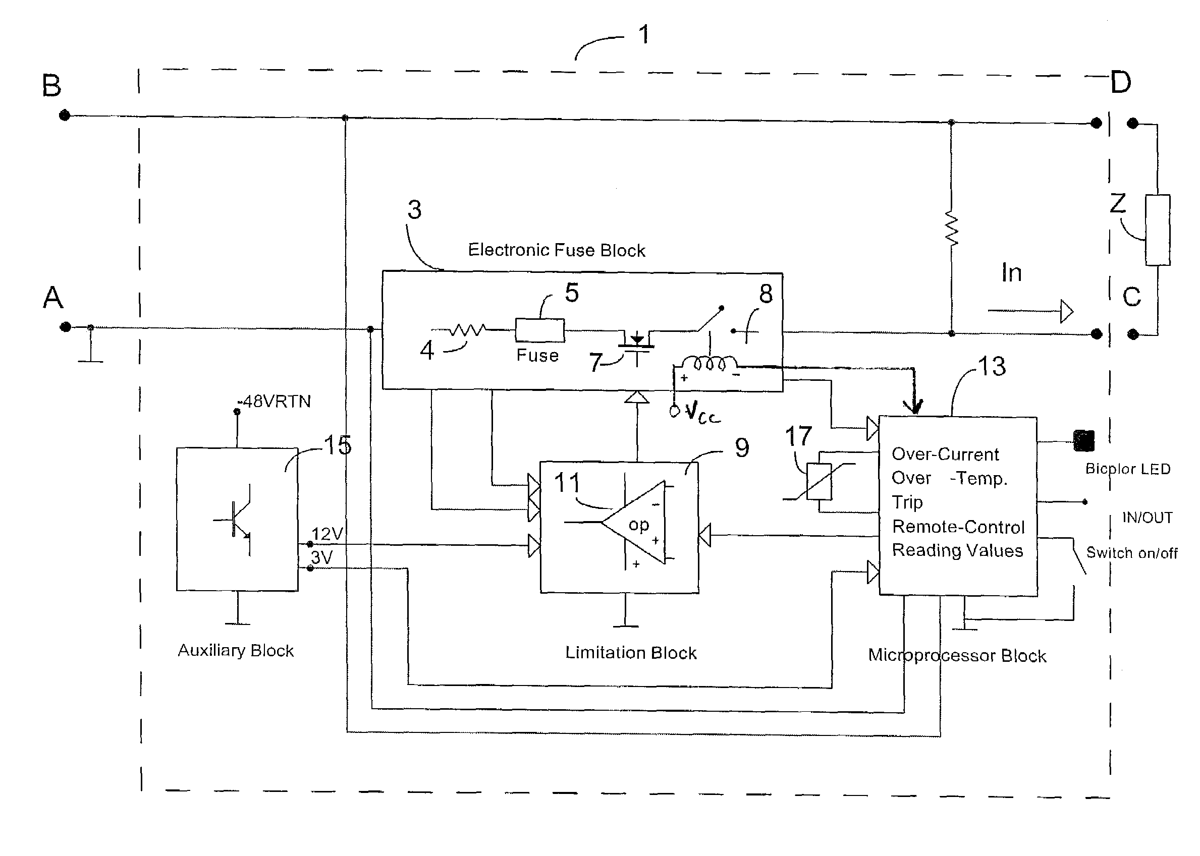
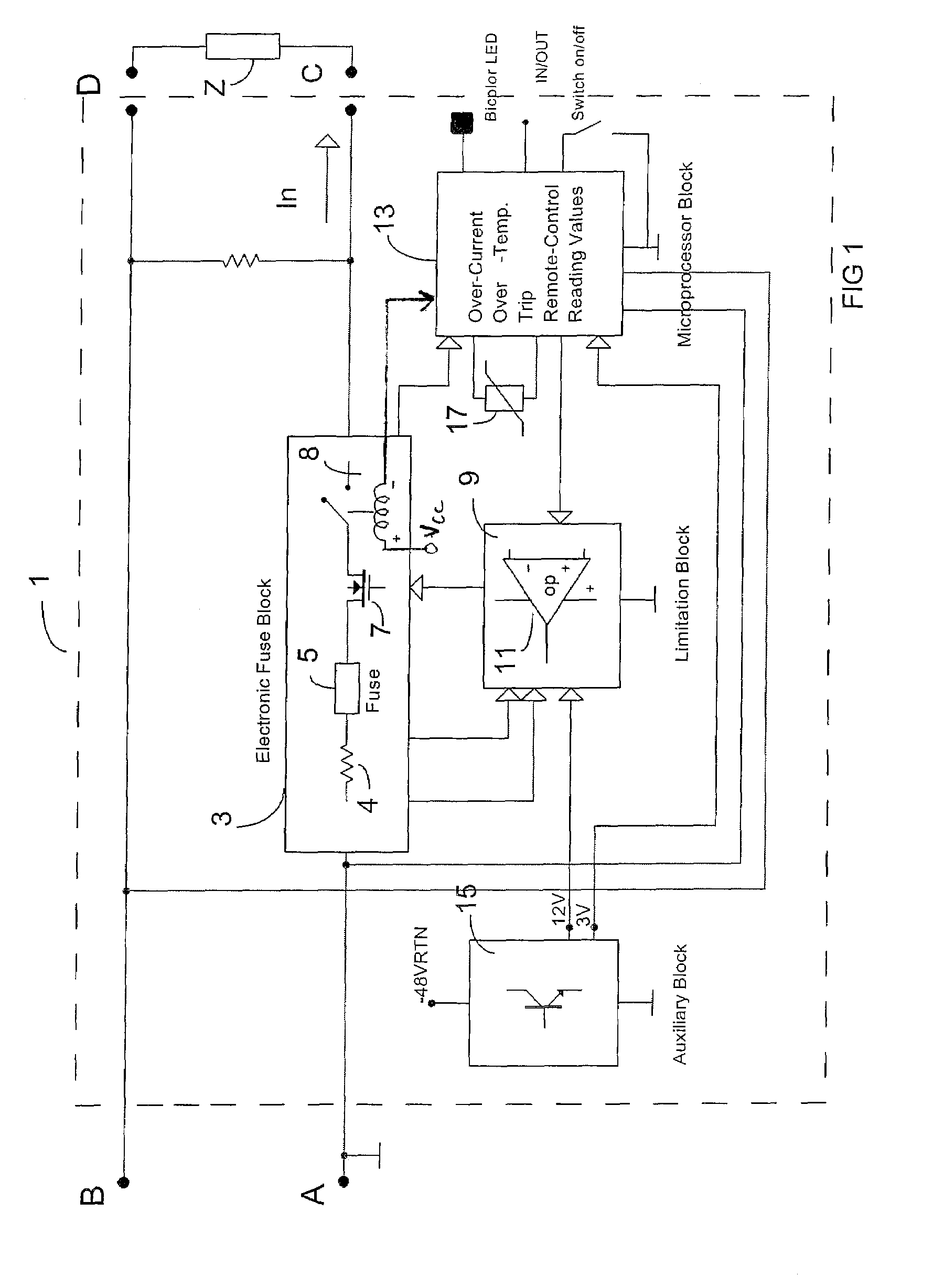
[0030]With reference initially to the diagram in FIG. 1, the circuit breaker 1 has an input having two terminals, A and B, and an output having two terminals, C and D. In circuit with line A-C is an interrupt block 3, which contains a current-sensing resistor 4, by means of which the current that traverses the circuit breaker 1 and that supplies a load circuit, or load, which is connected between the output terminals C and D, is read. The interrupt block 3 also includes at least one fuse 5, an electronic switch 7, and a relay 8. The fuse 5 constitutes a so-called “catastrophic protection”. The fuse 5 opens to definitively interrupt current flow, for example, in the event of a short circuit. In this case, the circuit breaker 1 must be replaced, or at least the fuse 5 must be replaced, whereas in other tripping situations, as will be clarified below, it is sufficient to reset the circuit breaker 1 that has tripped on account of an over-current condition. Similar to the fuse 5, the rel...


PUM


Abstract

An electronic circuit breaker includes an input for connection to a power-supply and an output for connection to a load. Connected in circuit between the input and the output are a switch, a relay, and a limitation block, which controls the switch to cause at least partial inhibition thereof in the event of an over-current condition. Also provided is a microprocessor which is connected to the limitation block to inhibit power supply to the load.

Description

CROSS-REFERENCES TO RELATED APPLICATIONS[0001]This application is a Continuation-In-Part application which claims benefit of co-pending U.S. Patent Application Serial No. PCT / IT2003 / 000155 filed Mar. 14, 2003, entitled “Electronic Circuit Breaker”; U.S. patent application Ser. No. 10 / 246,513 filed Sep. 18, 2002, entitled “Electronic Circuit Breaker”, and U.S. patent application Ser. No. 11 / 055,531 filed Feb. 10, 2005, entitled “Electronic Circuit Breaker”, all of which are hereby incorporated by reference.STATEMENT REGARDING FEDERALLY SPONSORED RESEARCH OR DEVELOPMENT[0002]Not ApplicableREFERENCE TO SEQUENCE LISTING OR COMPUTER PROGRAM LISTING APPENDIX[0003]Not ApplicableBACKGROUND OF THE INVENTION[0004]The present invention relates to an electronic circuit breaker for interrupting an electric power supply to a load when the current exceeds a pre-set value, for instance in the case of a short circuit.[0005]There currently exist various types of circuit breakers for protecting circui...

Claims


Application Information

Patent Timeline
Patent Type & Authority Patents(United States)
IPC IPC(8): H02H9/08H02H3/00H02H3/02H02H3/08H02H3/087
CPCH02H3/087H02H3/08H02H3/025H02H3/006
Inventor FIESOLI, GUIDOBITTONI, FRANCESCOCINCINELLI, LORENZO
Owner ABB (SCHWEIZ) AG
Why Eureka
Try Eureka