Spatial disassembly processor

a spatial disassembly and processor technology, applied in the direction of electrical apparatus, stereophonic systems, stereophonic arrangments, etc., can solve the problems of limited separation between output channels, inability of steered systems to simultaneously produce sound at several locations, and no single mathematical model accurately describes localization over the entire hearing range, so as to achieve easy incorporation

Active Publication Date: 2009-12-08
BOSE CORP
View PDF13 Cites 298 Cited by
  • Summary
  • Abstract
  • Description
  • Claims
  • Application Information

AI Technical Summary

Benefits of technology

[0027](5) Frequency dependent localization behavior of the human auditory system can be easily incorporated since signals are processed in narrow frequency bands.

Problems solved by technology

This process is known as dematrixing, and suffers from limited separation between the output channels.
Steered systems are therefore incapable of simultaneously producing sound at several locations.
No single mathematical model accurately describes localization over the entire hearing range.
They all have shortcomings, and do not always predict the correct subjective localization of a sound.

Method used


Image

  • Spatial disassembly processor
  • Spatial disassembly processor
  • Spatial disassembly processor

Examples


Embodiment Construction

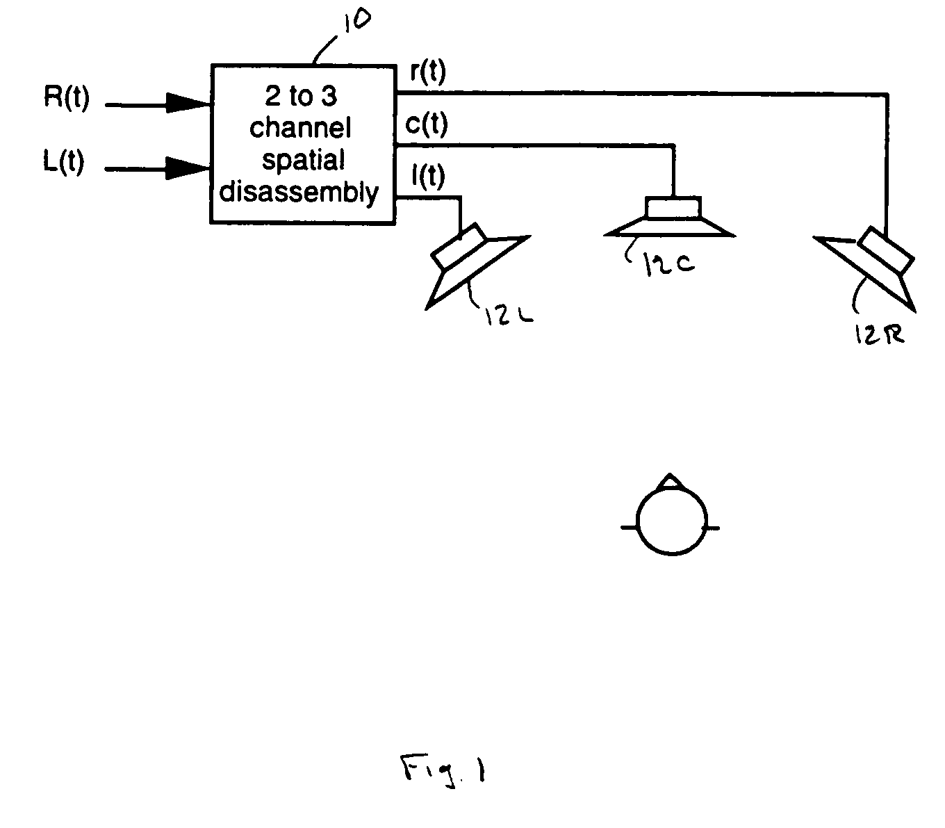
[0032]The described embodiment is of a 2 input-3 output spatial disassembly system. The stereo input signals L(t) and R(t) are processed by a 2 to 3 channel spatial disassembly processor 10 to yield three output signals l(t), c(t), and r(t) which are reproduced over three speakers 12L, 12C and 12R, as shown in FIG. 1. The center output speaker 12C is assumed to lie midway between the left and right output speakers.

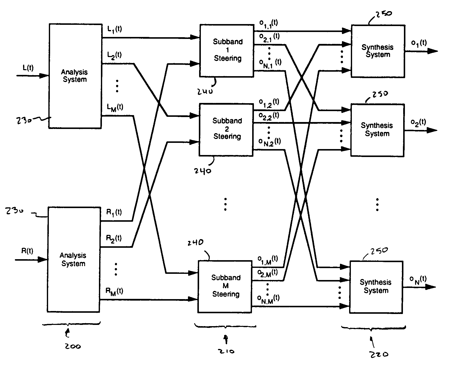
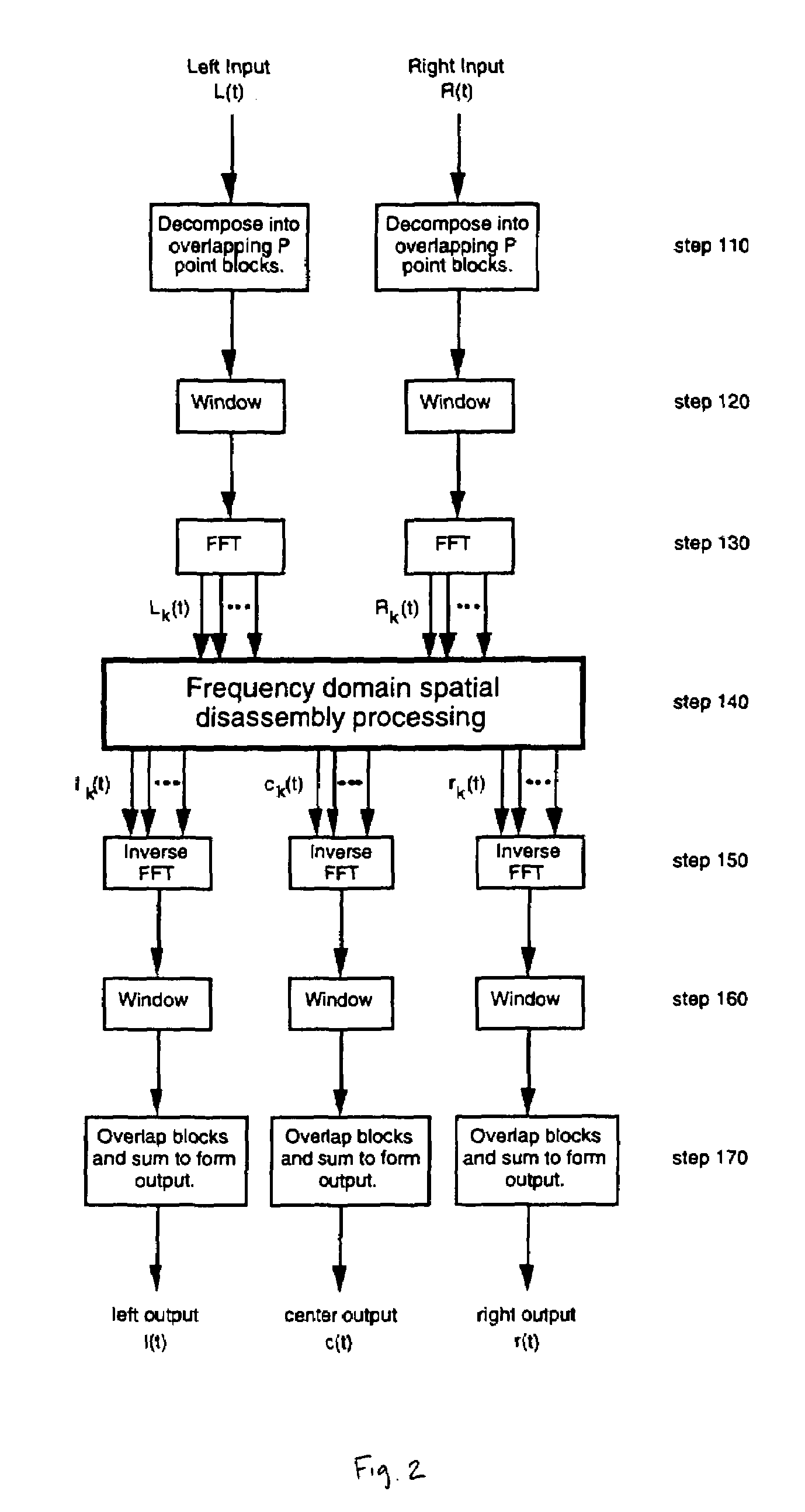
[0033]The described embodiment employs a Short-Term Fourier Transform (STFT) in the analysis and synthesis steps of the algorithm. The STFT is a well-known digital signal processing technique for splitting signals into a multitude of frequency components in an efficient manner. (Allen, J. B., and Rabiner, L. R., “A Unified Approach to Short-Term Fourier Transform Analysis and Synthesis,” Proc. IEEE, Vol. 65, pp. 1558-1564, November 1977.) The STFT operates on blocks of data, and each block is converted to a frequency domain representation using a fast Fourier transform (FF...


PUM


Abstract

A method of disassembling a pair of input signals L(t) and R(t) to form subband representations of N output channel signals o1(t), o2(t), . . . , oN(t), wherein t is time. The method includes the steps of generating a subband representation of the signal L(t) containing a plurality of subband components Lk(t) where k is an integer ranging from 1 to M; generating a subband representation of the signal R(t) containing a plurality of subband components Rk(t); and constructing the subband representation for each of the plurality of output channel signals, each of those subband representations containing a plurality of subband components oj,k(t), wherein oj,k(t) represents the kth subband of the jth output channel signal and is constructed by combining components of the input signals L(t) and R(t) according to an output construction rule: oj,k(t)=f(Lk(t),Rk(t)) for k=1, 2, . . . , M and j=1, 2, . . . , N.

Description

BACKGROUND OF THE INVENTION[0001]This invention relates to a method and apparatus for spatially disassembling signals, such as stereo audio signals, to produce additional signal channels.[0002]In the field of audio, spatial disassembly is a technique by which the sound information in the two channels of a stereo signal are separated to produce additional channels while preserving the spatial distribution of information which was present in the original stereo signal. Many methods for performing spatial disassembly have been proposed in the past, and these methods can be categorized as being either linear or steered.[0003]In a linear system, the output channels are formed by a linear weighted sum of phase shifted inputs. This process is known as dematrixing, and suffers from limited separation between the output channels. “Typically, each speaker signal has infinite separation from only one other speaker signal, but only 3 dB separation from the remaining speakers. This means that si...

Claims


Application Information

Patent Timeline
Patent Type & Authority Patents(United States)
IPC IPC(8): H04R5/00
CPCH04S7/30H04S2400/05
Inventor BECKMAN, PAUL E.ARNOLD, FINN A.
Owner BOSE CORP
Why Eureka
Try Eureka