Dedicated power supply apparatus, terminal, power supply system, and power supply method

a technology of dedicated power supply and terminal, which is applied in the direction of electric variable regulation, process and machine control, instruments, etc., can solve the problems of unstable operation of inability to receive power of 500 a or less from usb adapters, and nothing done for d+ and d terminals for data transmission, etc., to achieve safe charging system and safe charging system

Active Publication Date: 2009-12-08
SONY CORP
View PDF6 Cites 13 Cited by
  • Summary
  • Abstract
  • Description
  • Claims
  • Application Information

AI Technical Summary

Benefits of technology

[0010]In view of the above-described problems, it is desirable to provide a dedicated power supply apparatus, a terminal, a power supply system, and a power supply method capable of providing a safe charging system and suppressing malfunction or unstable operation of the terminal while the dedicated power supply apparatus is being connected.
[0012]With this structure, the two signal lines can be pulled up to a predetermined voltage by placing each of the two resistors between the regulator and an associated one of the two signal lines. Accordingly, a device connected to the dedicated power supply apparatus is prevented from mistakenly recognizing that the dedicated power supply apparatus has been suspended, and this device is thereby prevented from being suspended. Thus, malfunction or unstable operation of the device can be suppressed, and a safe charging system can be provided.
[0022]With this system, in the dedicated power supply apparatus, the two signal lines can be pulled up to a predetermined voltage by placing each of the two resistors between the regulator and an associated one of the two signal lines. Accordingly, a device connected to the dedicated power supply apparatus is prevented from being suspended. The terminal determines whether a signal, such as SOF, indicating that data transmission is performed is transmitted. On the basis of the determination result, the terminal determines whether the connection destination device is the dedicated power supply apparatus, such as a USB adapter. Accordingly, the terminal can perform appropriate charging. In this manner, malfunction or unstable operation of the terminal can be suppressed, and a safe charging system can be provided.
[0024]With this method, after starting charging, the terminal detects a signal, such as SOF, indicating that the external device performs data transmission. On the basis of the detection result, the terminal controls charging. In this manner, malfunction or unstable operation of the terminal connected to a dedicated power supply apparatus can be suppressed, and a safe charging system can be provided.
[0025]According to the embodiments of the present invention, the dedicated power supply apparatus includes the two resistors, each placed between the regulator and an associated one of the two signal lines. Thus, the two signal lines can be pulled up to a predetermined voltage. Also, a device connected to the dedicated power supply apparatus is prevented from being suspended. The terminal determines whether a signal, such as SOF, indicating that data transmission is performed is transmitted. The terminal can perform appropriate charging when it is determined that the communication destination device is the dedicated power supply apparatus, such as a USB adapter. In this manner, malfunction or unstable operation of the terminal can be suppressed, and a safe charging system can be provided.

Problems solved by technology

Thus, the operation of the D+ and D− terminals is unstable.
When the mobile device mistakenly recognizes that the USB adapter has been suspended, the mobile device can only receive power of 500 μA or less from the USB adapter.
In known USB adapters, however, nothing has been done for the D+ and D− terminals for data transmission, and hence the mobile device may mistakenly recognize that the USB adapter has been suspended.

Method used


Image

  • Dedicated power supply apparatus, terminal, power supply system, and power supply method
  • Dedicated power supply apparatus, terminal, power supply system, and power supply method
  • Dedicated power supply apparatus, terminal, power supply system, and power supply method

Examples


Embodiment Construction

[0038]With reference to the accompanying drawings, a dedicated power supply apparatus, a terminal, a power supply system, and a power supply method according to preferred embodiments of the present invention will be described in detail. In the specification and the drawings, elements that have substantially the same functions are denoted by the same reference numerals, and repeated descriptions thereof will be omitted.

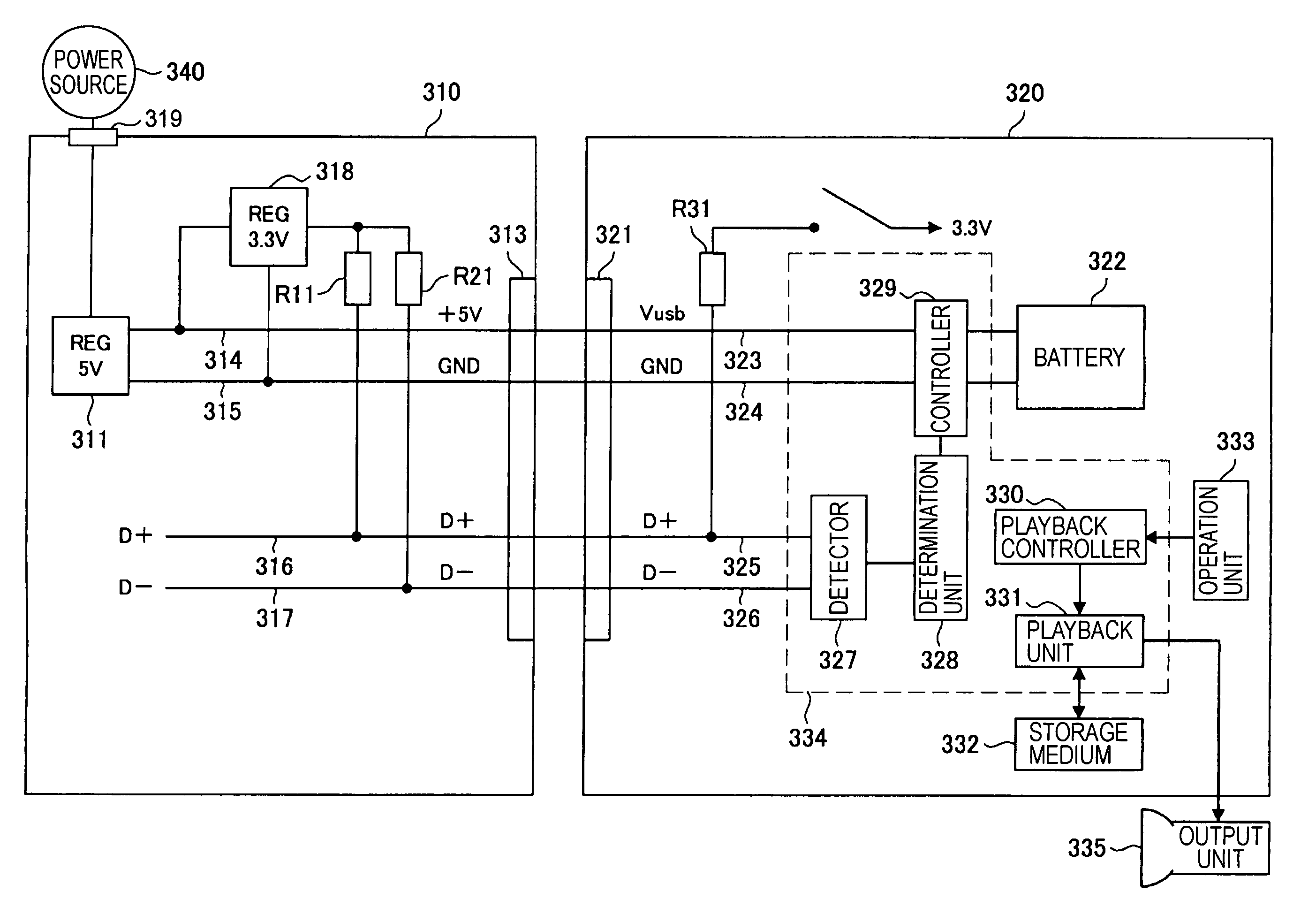
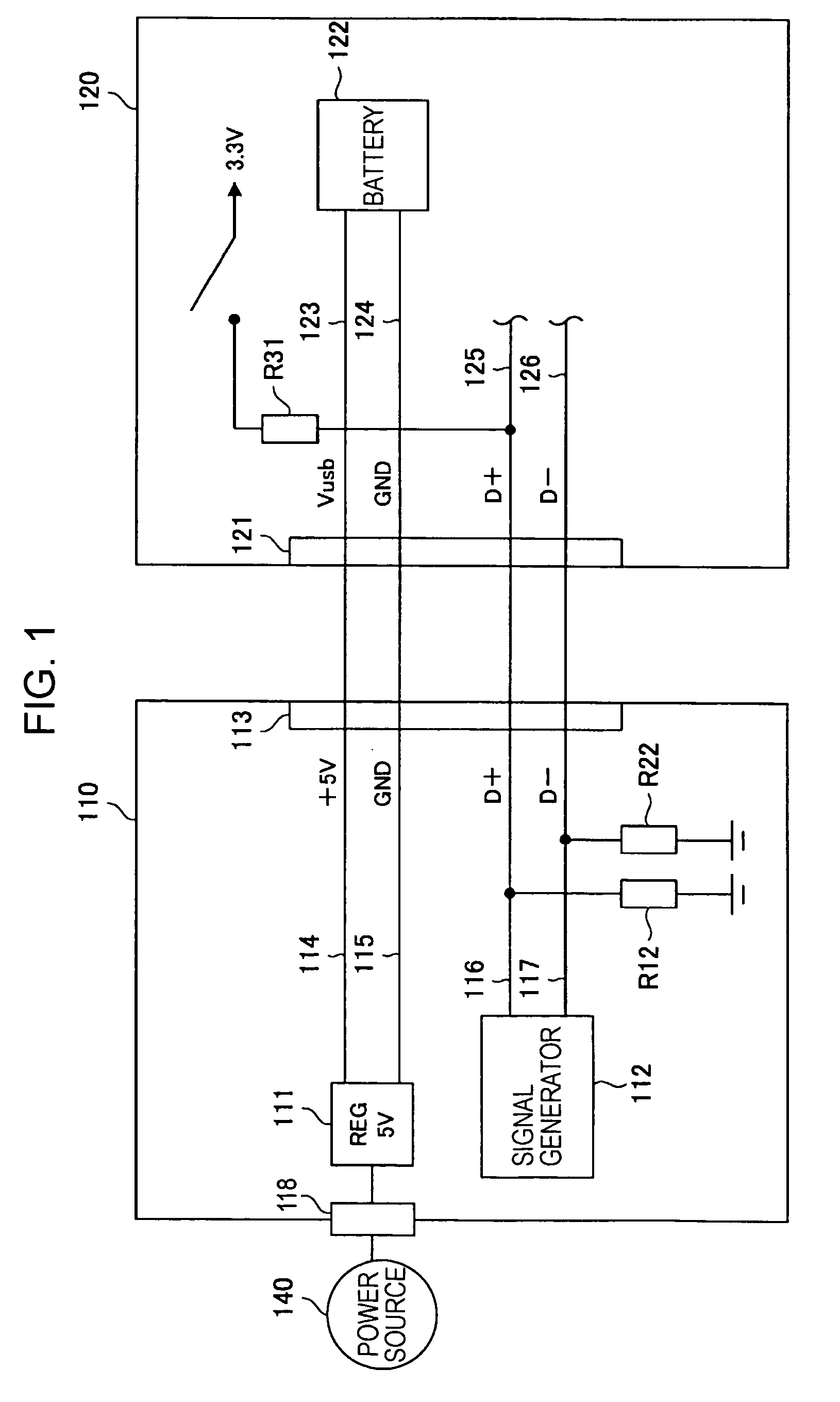
[0039]According to an embodiment of the present invention, a dedicated power supply apparatus for charging a battery that is included in a device and can be recharged by establishing a USB connection (hereinafter referred to as a “USB adapter”) will be described. In this embodiment, the term “device” refers to a device that can receive power from a computer, which is a USB host, or from the USB adapter by establishing a connection via USB. The device in the embodiment mainly assumes a mobile device that can be carried around. However, the device is not limited to that ...


PUM


Abstract

A terminal for a power supply system is disclosed. The terminal may have a connection portion, a battery that receives power from an external device via the connection portion, and a detector that detects a data signal from the external device. The terminal may also have a determination unit, a current converter that selectively converts an amount of charging current from a first current to a second current larger than the first current, and a controller that controls charging of the battery on the basis of a determination result. The controller is configured to control the current converter to charge the battery with the first current when the determination unit determines the external device is not a dedicated power supply, and to control the current converter to charge the battery with the second current when the determination unit determines the external device is a dedicated power supply.

Description

CROSS REFERENCES TO RELATED APPLICATIONS[0001]The present invention contains subject matter related to Japanese Patent Application JP 2005-251543 filed in the Japanese Patent Office on Aug. 31, 2005, the entire contents of which are incorporated herein by reference.BACKGROUND OF THE INVENTION[0002]1. Field of the Invention[0003]The present invention relates to dedicated power supply apparatuses, terminals, power supply systems, and power supply methods, and in particular, to a power supply technique applicable to mobile devices that can be carried around.[0004]2. Description of the Related Art[0005]A rapidly increasing number of mobile devices, such as digital audio players, that are small and can be carried around are being widely used. Many of these mobile devices are capable of performing high-speed data communication with computers by establishing universal serial bus (USB) connections. There are various methods for charging a battery in such a mobile device. For example, one me...

Claims


Application Information

Patent Timeline
Patent Type & Authority Patents(United States)
IPC IPC(8): G06F1/26H02J7/00
CPCH02J7/0073H02J7/007H02J2007/006H02J2207/30H02J7/0071H02J7/02
Inventor IRIE, KENJI
Owner SONY CORP
Why Eureka
Try Eureka