Hand-guided sweeper

a technology of hand-guided sweepers and cleaning brushes, which is applied in the direction of carpet cleaners, applications, construction, etc., can solve the problems of slight retrofit complexity, and achieve the effects of light retrofit complexity, simple adjustment, and low cos

Inactive Publication Date: 2009-12-15
BADSTRASSE 115
View PDF5 Cites 3 Cited by
  • Summary
  • Abstract
  • Description
  • Claims
  • Application Information

AI Technical Summary

Benefits of technology

[0004]It is an object of the invention to provide a hand-guided sweeper which permits an adaptation of the handle elevation and the running direction of the sweeper in a simple manner.
[0006]The sweeper brush is displaceable about an axis referred to the ground. In this way, it is ensured that the sweeper brush lies on the ground after the adjustment or displacement. An adjustment of the handles can be achieved advantageously in that the guide rod is adjusted about a horizontal axis. The position of the wheels and the brush remains the same so that the position of the sweeper brush on the ground is not influenced by the adjustment of the elevation of the handles.
[0007]It is practical to mount the first and second adjusting devices on a common connecting flange. In this way, it is especially possible to retrofit existing sweepers with little complexity with the adjusting devices. The complexity for the retrofit is slight because both adjusting devices are mounted on a common connecting flange.
[0008]Advantageously, the first adjusting device includes a pin which, in a first position of the adjusting device, is arranged in a first opening and, in a second position of the adjusting device, the pin is arranged in a second opening. In this way, a simple adjustability is provided. The openings define fixed adjusting positions so that the operator can undertake an adjustment to the desired position in a simple manner. Advantageously, the pin is held by a spring in the opening. For adjusting, the pin need only be moved against the force of the spring out of the one opening and moved to another opening where the pin automatically latches into place because of the force of the spring. The spring ensures also that the pin is held reliably in the opening. Advantageously, the first adjusting device has three openings which make possible an arrangement of the sweeper brush in three positions, namely: parallel to the running direction of the wheel, rotated in one direction by 15° relative to the running direction of the wheel and rotated in the other direction by 15° relative to the running direction of the wheel. It has been shown that dirt is swept only in one direction for a rotation of the sweeper brush by 15° relative to the running direction of the wheel so that an already cleaned surface does not become dirty again. When sweeping in the counter direction, the sweeper brush can be rotated in a simple manner by 15° relative to the running direction of the wheel in the opposite direction so that a dirtying of an already cleaned surface is avoided.
[0009]The first adjusting device is advantageously mounted on the end of the guide rod facing toward the sweeper brush. A rapid and ergonomic actuation of the adjusting device can be ensured in that the first adjusting device has an actuating element which extends up to the end of the guide rod facing away from the sweeper brush. The actuating element can then be reached by an operator standing in the region of the handles. The operator need not go to the other end of the guide rod. In this way, an ergonomic working by the operator and a rapid adjustment is possible. A simple and stable embodiment of the actuating element is obtained when the actuating element is configured as an actuating tube which is connected to the pin. The first adjusting device has a mounting flange which is attached to the connecting flange so as to be rotatable about the vertical axis and on which the actuating element is attached. Advantageously, the drive motor and the sweeper brush are connected to a common mount with a mounting flange. In this way, the adjusting devices can be retrofitted via a simple fixing of the mount to the mounting flange. In order to ensure an adequate stability of mounting flange and connecting flange, it is provided that the mounting flange and / or the connecting flange contain magnesium. According to a feature of the invention, the connecting flange and mounting flange are of magnesium.
[0010]Advantageously, the second adjusting device has toothed elements which are in engagement with each other. The first toothed element is advantageously connected to the connecting flange so that it cannot rotate relative thereto and the second toothed element is connected to the guide rod. The toothed elements are releasably clamped against each other. By loosening the tension or clamping force, the toothed elements can be rotated relative to each other so that the guide rod can be rotated relative to the connecting flange about a horizontal axis. A simple manipulation can be achieved in that the connecting flange is so pretensioned that the toothed elements can be rotated relative to each other when the clamping force is released. To adjust the guide rod, the clamping force need simply be relaxed or loosened and the guide rod can be rotated into the desired position. The guide rod is fixed by a renewed clamping of the toothed elements. With the configuration of the toothed elements, a good adjustability of the handle elevation is achieved with high stability and low weight of the adjusting device. Advantageously, the second adjusting device is configured to be mirror inverted to the center axis of the guide rod and has two pairs of toothed elements which are mounted on respective sides of the guide rod.

Problems solved by technology

The complexity for the retrofit is slight because both adjusting devices are mounted on a common connecting flange.

Method used


Image

  • Hand-guided sweeper
  • Hand-guided sweeper
  • Hand-guided sweeper

Examples


Embodiment Construction

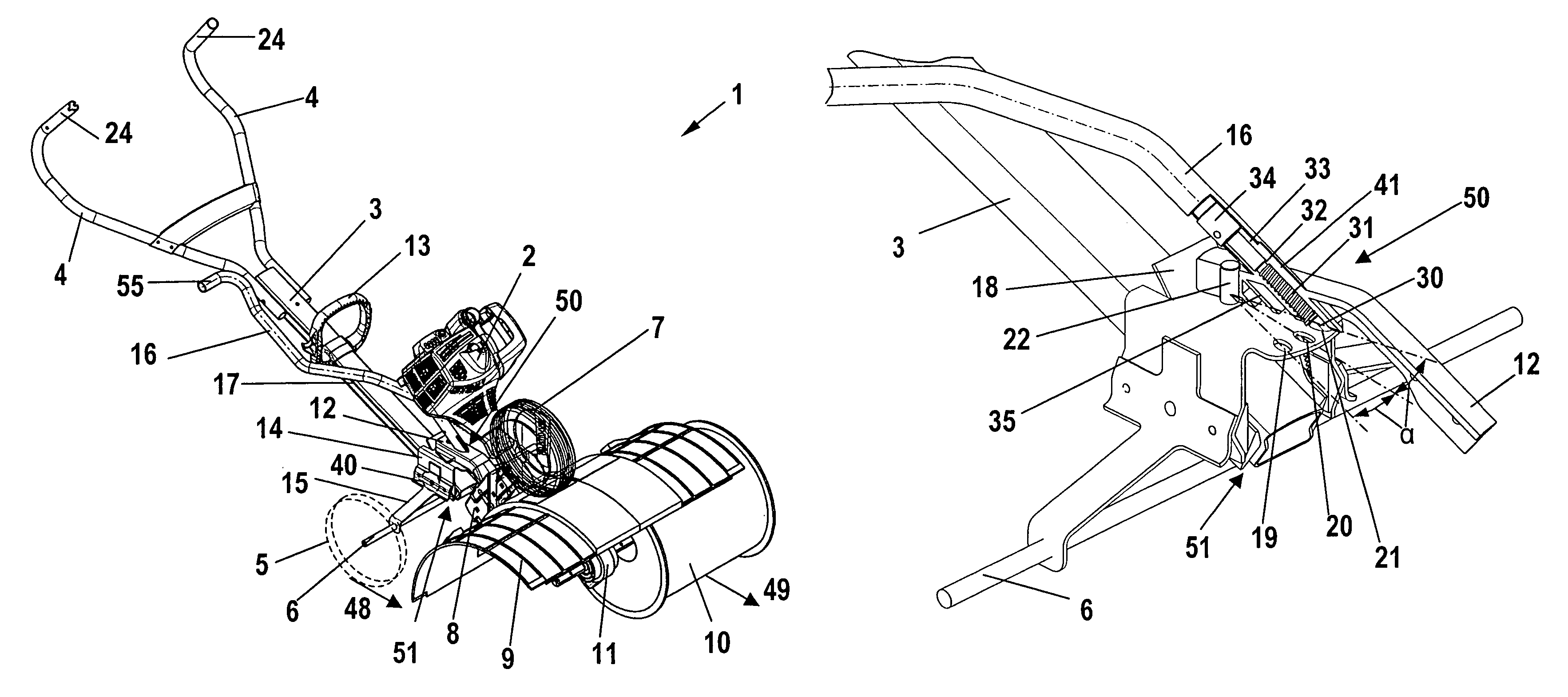
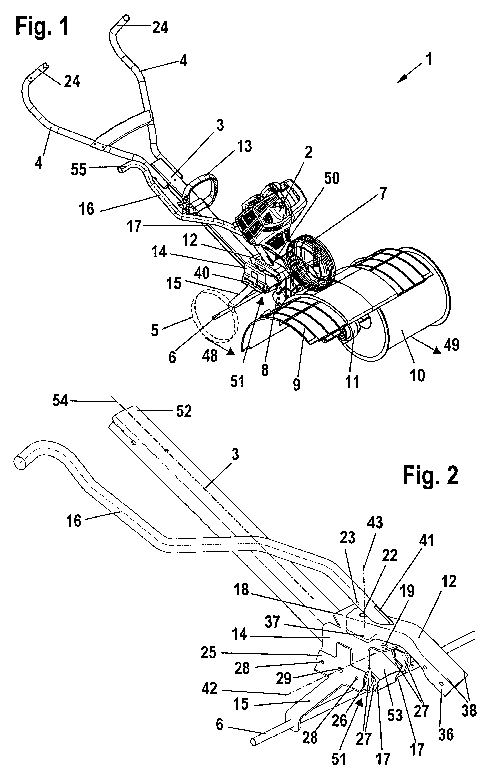
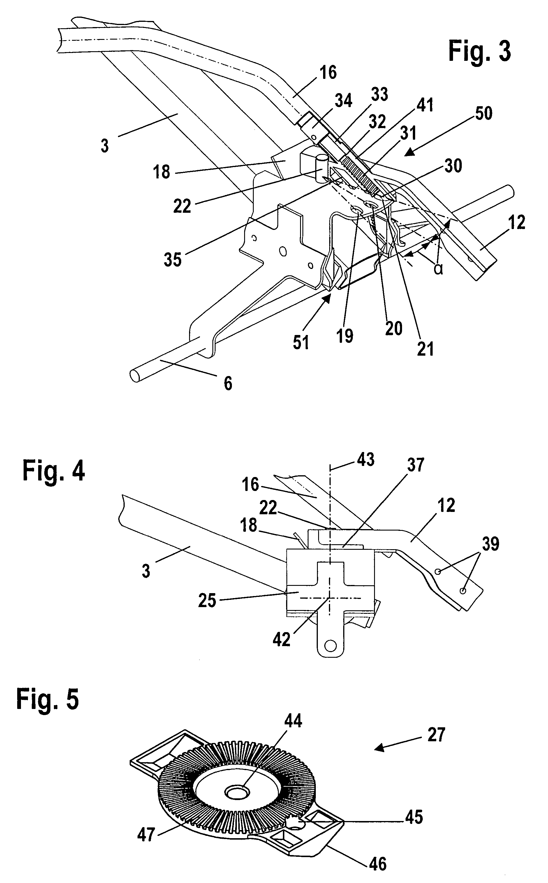
[0017]The sweeper 1 shown in FIG. 1 has a drive motor 2 such as a two-stroke engine which drives two sweeper brushes 10 in rotation via a flexible shaft (not shown) and a gear assembly 11. In FIG. 1, only one of the two sweeper brushes 10 is shown. The other sweeper brush 10 is arranged mirror symmetrically on the other side of the gear assembly 11. The two sweeper brushes 10 are partially surrounded by a protective cover 9. The drive motor 2 and the sweeper brushes 10 are fixed on a common mount 8. The mount 8 is attached to a mounting flange 12 at the bores 39 shown in FIG. 4. The mounting flange 12 is attached to a connecting flange 14 via a first adjusting device 50. A guide rod 3 is mounted on the connecting flange 14 via a second adjusting device 51. The adjusting devices50 and 51 are fixed at a first end 53 of the guide rod 3 (FIG. 2).

[0018]The drive motor 2 is arranged above the adjusting devices (50, 51) and thereby lies in the travel direction behind the sweeper brushes 10...


PUM


Abstract

A hand-guided sweeper (1) includes a guide rod (3) on which a handle (24) is mounted for guiding the sweeper (1) over the ground. The sweeper (1) has at least one sweeper brush (10), which is driven in rotation by a drive motor (2), and at least one wheel (5). The wheel (5) and the sweeper brush (10) lie against the ground during operation of the sweeper (1). The sweeper (1) has a first adjusting device (50) which permits an adjustment of the guide rod (3) relative to the sweeper brush (10) about a vertical axis (43) referred to the ground.

Description

CROSS REFERENCE TO RELATED APPLICATION[0001]This application claims priority of German patent application no. 10 2004 042 708.9, filed Sep. 3, 2004, the entire content of which is incorporated herein by reference.BACKGROUND OF THE INVENTION[0002]United States patent publication US 2005 / 0045347 A1 discloses a hand-guided work apparatus such as a sweeper. The work apparatus includes a guide rod for guiding the work apparatus over the ground and a work tool which is driven in rotation by a drive motor. Two wheels are provided for guiding the work apparatus over the ground. The wheels can be adjusted in order to make possible an adjustment in elevation. However, this causes the elevation of the handles of the work apparatus to change.[0003]It has been shown that, for a sweeper, an inclination of the running direction of the sweeper brush relative to the running direction of the wheels is advantageous because, in this way, a dirtying of an already cleaned ground surface can be avoided. T...

Claims


Application Information

Patent Timeline
Patent Type & Authority Patents(United States)
IPC IPC(8): E01H1/02A47L11/24
CPCE01H1/056
Inventor STARK, THOMASKOALICK, JAN
Owner BADSTRASSE 115
Why Eureka
Try Eureka