Method and system for reduction of jet engine noise

a technology for jet engines and noise reduction, applied in the direction of machines/engines, mechanical equipment, transportation and packaging, etc., can solve the problems of aircraft engine noise, fan noise, and significant problem of aircraft us

Active Publication Date: 2009-12-15
GENERAL ELECTRIC CO
View PDF16 Cites 46 Cited by
  • Summary
  • Abstract
  • Description
  • Claims
  • Application Information

AI Technical Summary

Problems solved by technology

Aircraft engine noise is a significant problem in high population areas and noise-controlled environments.
These restrictions range from financial penalties and schedule restrictions to an outright ban on the use of the aircraft.
The fan is a source of noise since the fan blades pushing through the air cause noise.
These stators are a large source of noise as the wakes of air from fan flow slap against the stators.
The unsteadiness in the fan flow (turbulence) interacts with the stators to create broadband noise.
Combustion is another source of noise.
Since the turbine tends to look and act like a set of alternating rotors and stators, this is another source of noise.
The interaction of jet exhausts with the surrounding air generates broadband noise.
Reduction of fan tip speed is a further noise reduction technique but has proved to be limiting relative to fan performance.
These techniques, however, require engine redesign and may significantly affect engine performance.
However, fan and compressor noise radiating from the engine inlet remains a problem.
In fact, as turbine engines evolved from turbojet to turbofan engines, fan noise has become an increasingly large contributor of total engine noise.
For high bypass ratio engines currently in use, fan noise dominates the total noise on approach and on takeoff.
More specifically, the fan inlet noise is a major contributor to the total noise on approach, and the fan exhaust noise is dominant on takeoff.
Acoustic wall treatment have been even less effective in reducing fan inlet noise than reducing fan exhaust noise.
That is, absorptive liners are effective for attenuating high mode order noise, but are inefficient for attenuating low mode order noise, i.e., those noise wave fronts traveling along the duct at a low angular displacement relative to the duct walls.

Method used


Image

  • Method and system for reduction of jet engine noise
  • Method and system for reduction of jet engine noise
  • Method and system for reduction of jet engine noise

Examples


Embodiment Construction

[0020]Exemplary embodiments are described with reference to specific configurations. Those of ordinary skill in the art will appreciate that various changes and modifications can be made while remaining within the scope of the appended claims. Additionally, well-known elements, devices, components, methods, process steps and the like may not be set forth in detail in order to avoid obscuring the invention.

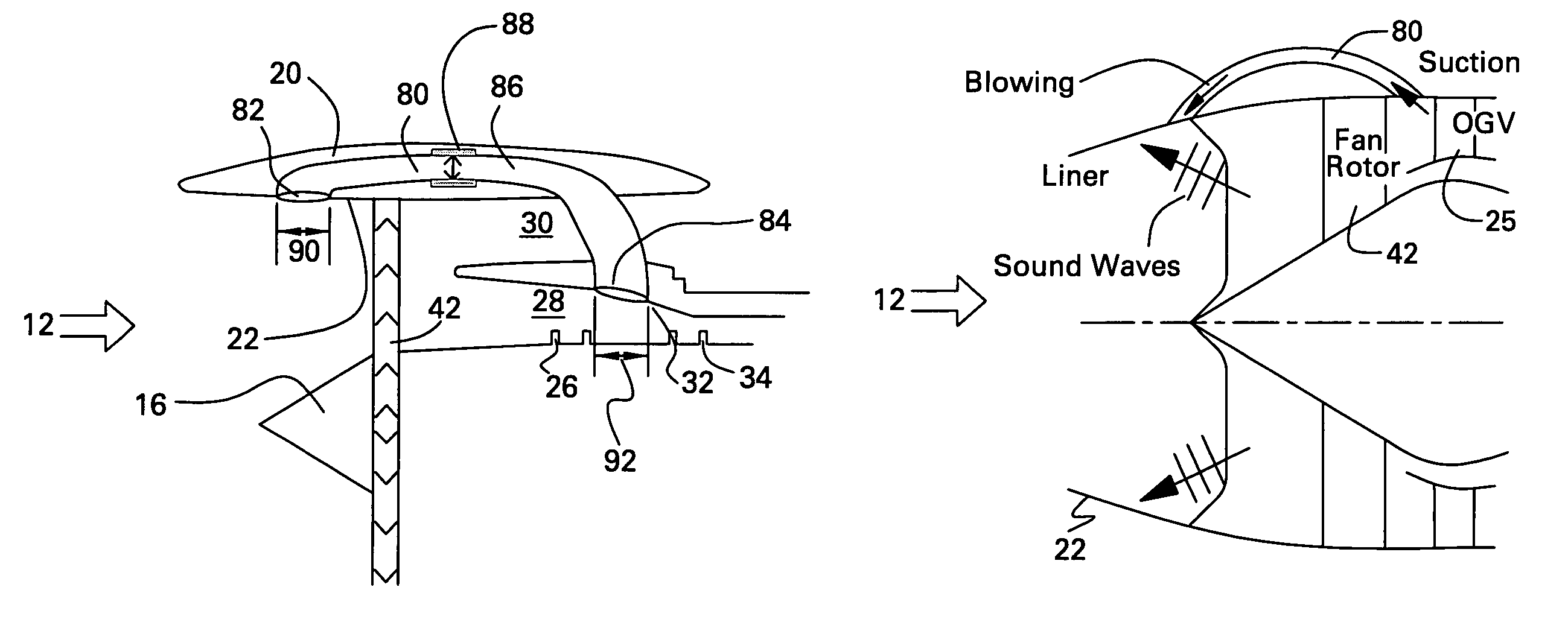
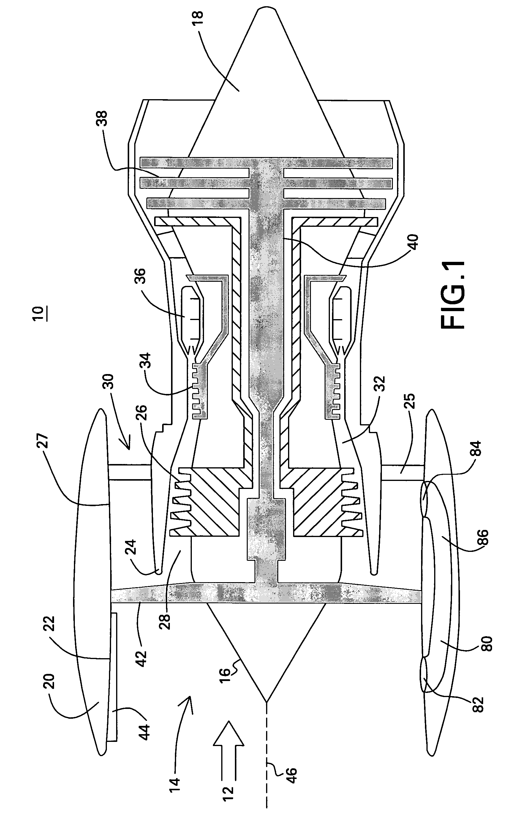
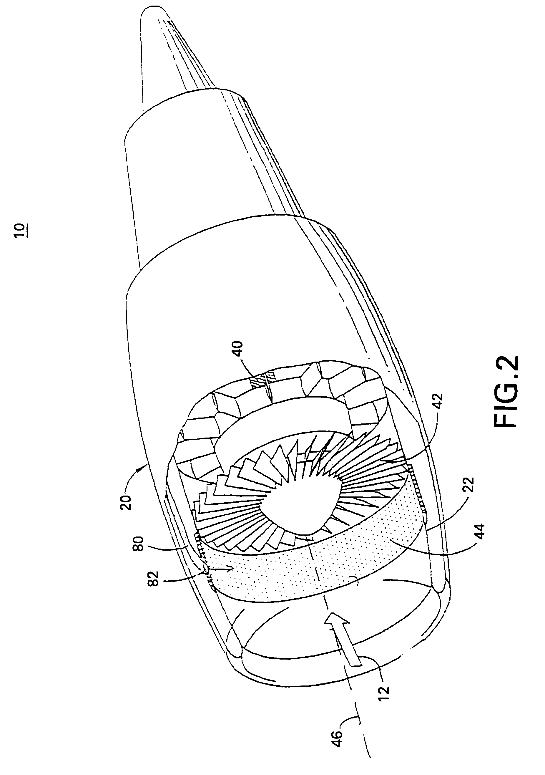
[0021]A method and system of attenuating jet engine noise is described herein. Features of the discussion and claims may be applied to various classes of engines including, turbojets, turbofans, turbopropellers, turboshafts, ramjets, rocket jets, pulse-jets, turbines, gas turbines, steam turbines, commercial engines, corporate engines, military engines, marine engines, etc. As used herein “jet engine” includes engines other than, and in addition to, aircraft engines. In an embodiment, a method and system of attenuating sound from an inlet fan duct and from a bypass flow duct is des...


PUM


Abstract

In an aspect, a method is provided for attenuating jet engine noise. Air velocity, adjacent to an inlet fan duct outer wall, is increased to a greater rate than typical velocity of an operational engine ambient inlet airflow, adjacent to the inlet fan duct outer wall. Boundary layer and associated turbulence is reduced or eliminated. Refraction and absorption of inlet sound into an acoustic liner is optimized. In an aspect, air velocity is increased by injecting air. In an aspect, air velocity is increased by exerting a suction force. In an aspect, a system is provided to attenuate jet engine noise. In an aspect, a fluid duct is provided opening to an inlet fan duct outer wall and to aft of a fan rotor.

Description

FIELD OF THE INVENTION[0001]The invention relates to jet engine noise, and more particularly to attenuating jet engine noise utilizing fluidic control.BACKGROUND OF THE INVENTION[0002]Aircraft engine noise is a significant problem in high population areas and noise-controlled environments. Noise generated by aircraft engines during takeoff and landing is a matter of public concern in most parts of the world. Because of the adverse impact noise has on the environment, many countries have imposed strict noise emission standards on aircraft. In the United States, the Federal Aviation Administration has imposed strict noise emission standards that place stringent operating restrictions on aircraft that are currently in use. These restrictions range from financial penalties and schedule restrictions to an outright ban on the use of the aircraft. An effective and efficient method of noise attenuation is necessary since these restrictions severely curtail the useful life of certain types o...

Claims


Application Information

Patent Timeline
Patent Type & Authority Patents(United States)
IPC IPC(8): F02K3/02B64D33/00B64D29/06F02C7/045F02K3/06
CPCB64D33/02F02K3/06F02C7/045B64D2033/0206B64D2033/0286F05D2250/51F05D2260/962
Inventor MANI, RAMANIGRAZIOSI, PAOLO
Owner GENERAL ELECTRIC CO
Why Eureka
Try Eureka