External profile for turbine blade airfoil

a turbine blade and airfoil technology, applied in the field of turbine blades, can solve the problems of increasing complexity of cooling circuit configurations required for trailing edges, increasing complexity of cooling circuit configurations for trailing edges, and increasing complexity of ceramic cores used to form trailing edge cooling circuits

Inactive Publication Date: 2009-12-15
SIEMENS ENERGY INC
View PDF9 Cites 17 Cited by
  • Summary
  • Abstract
  • Description
  • Claims
  • Application Information

AI Technical Summary

Problems solved by technology

As turbine inlet temperatures increase and the pressure ratio across the turbine stage becomes higher, the cooling schemes for the first stage blades become more complicated.
In particular, in order to enhance the cooling efficiency at the trailing edges of the blade airfoils, the cooling circuit configurations required for the trailing edges becomes increasingly intricate.
As a consequence, the ceramic cores that are used to form the trailing edge cooling circuits have become more complex and fragile, with an associated complexity in the manufacturing process.

Method used


Image

  • External profile for turbine blade airfoil
  • External profile for turbine blade airfoil
  • External profile for turbine blade airfoil

Examples


Embodiment Construction

[0014]In the following detailed description of the preferred embodiment, reference is made to the accompanying drawings that form a part hereof, and in which is shown by way of illustration, and not by way of limitation, a specific preferred embodiment in which the invention may be practiced. It is to be understood that other embodiments may be utilized and that changes may be made without departing from the spirit and scope of the present invention.

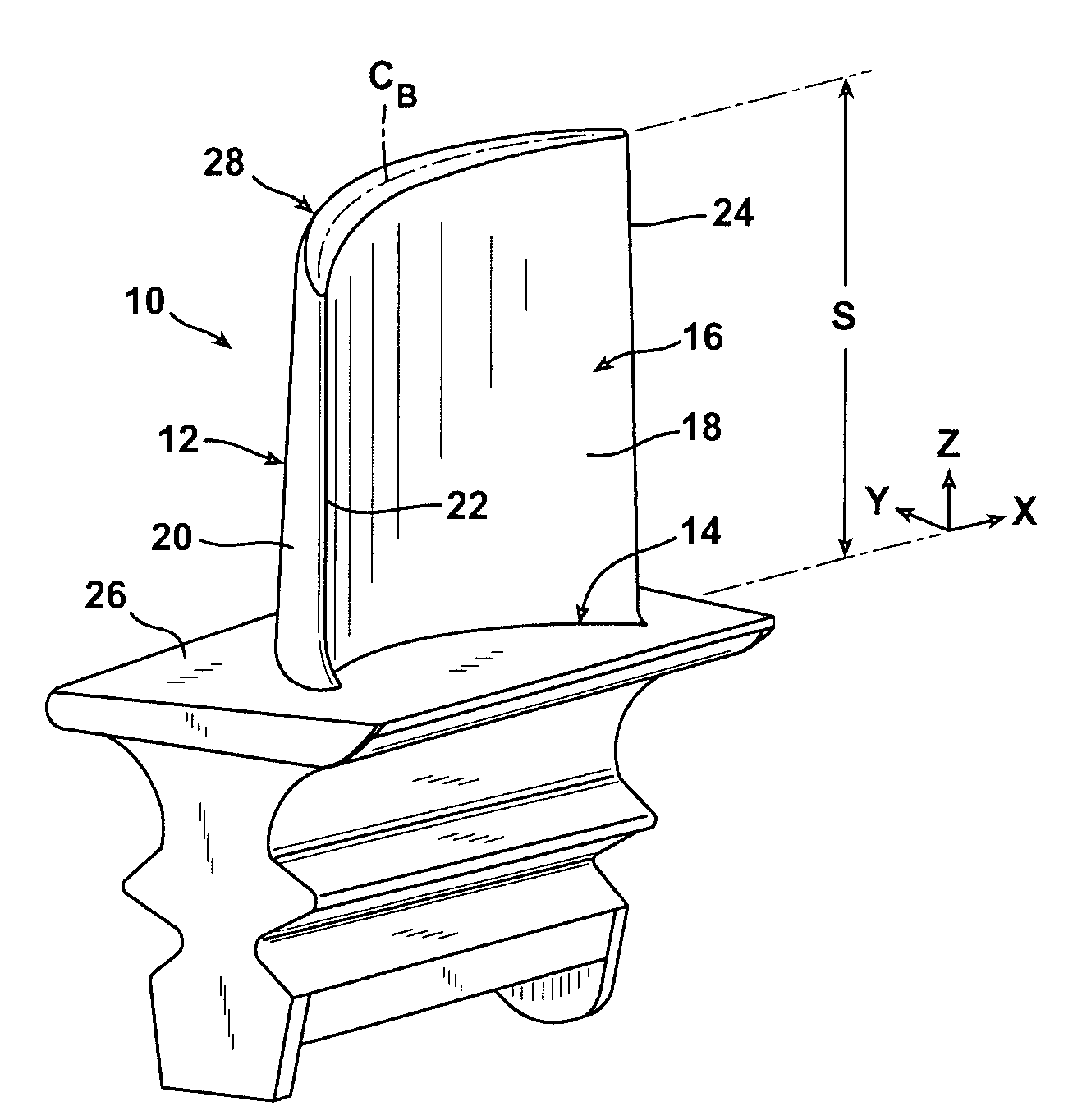
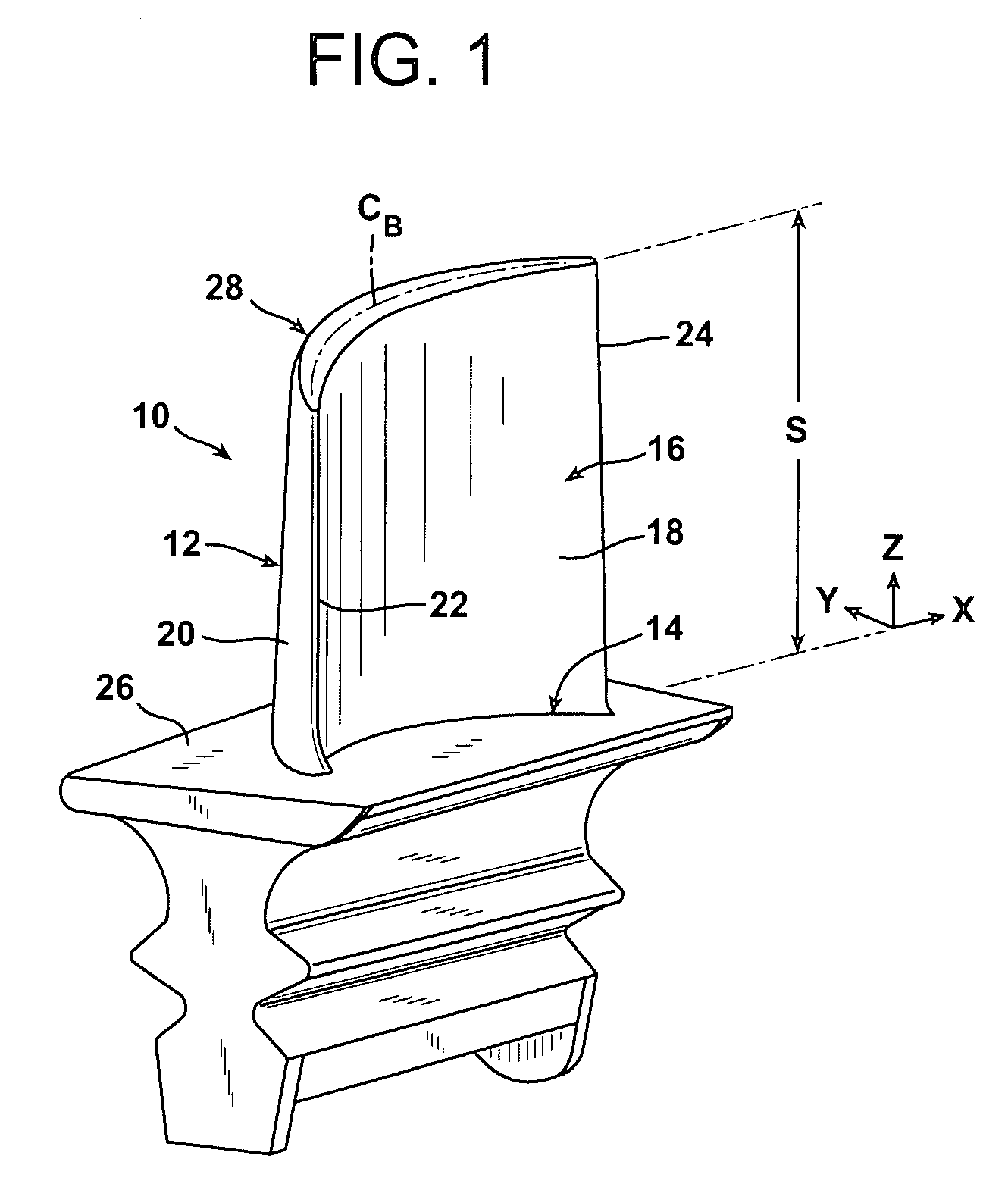
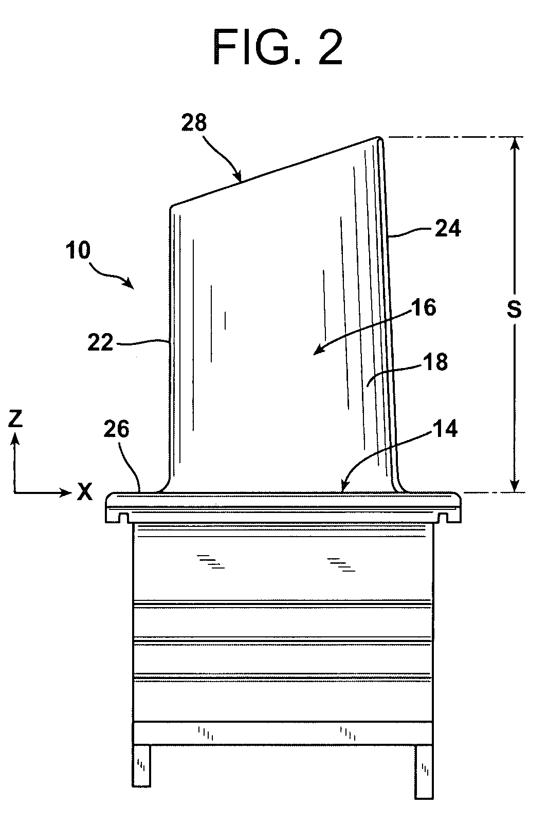
[0015]Referring to FIGS. 1 and 2, an exemplary turbine blade 10 for the first stage in a gas turbine engine is illustrated. The blade 10 includes an airfoil 12 and a root 14 which is used to conventionally secure the blade 10 to a rotor disk of the engine for supporting the blade 10 in the working medium flow path of the turbine where working medium gases exert motive forces on the surfaces thereof. The airfoil 12 has an outer wall 16 comprising a pressure sidewall 18 and a suction sidewall 20. The pressure and suction sidewalls 18, 20 a...


PUM


Abstract

A turbine blade including an airfoil having a pressure sidewall and a suction sidewall joined together along an upstream leading edge and a downstream trailing edge. The leading edge and trailing edge are formed as substantially straight edges, and portions of the pressure sidewall and suction sidewall adjacent the trailing edge form substantially planar surfaces. The airfoil has an uncoated nominal profile substantially in accordance with Cartesian coordinate values of X, Y and Z set forth in Table 1 wherein Z represents a perpendicular distance from a plane normal to a radius of a turbine centerline and containing the X and Y values with the Z value commencing at zero in the X, Y plane at a radially innermost aerodynamic section of the airfoil, and X and Y represent coordinate values defining the airfoil profile at each distance Z which, when connected by smooth continuing arcs, define profile sections at each distance Z.

Description

FIELD OF THE INVENTION[0001]The present invention relates to a turbine blade for a gas turbine stage and, more particularly, to a first stage turbine blade airfoil profile.BACKGROUND OF THE INVENTION[0002]In a turbomachine, such as a gas turbine engine, air is pressurized in a compressor then mixed with fuel and burned in a combustor to generate hot combustion gases. The hot combustion gases are expanded within the turbine section where energy is extracted to power the compressor and to produce useful work, such as powering a propeller for an aircraft in flight or turning a generator to produce electricity. The hot combustion gas travels through a series of turbine stages. A turbine stage may include a row of stationary vanes followed by a row of rotating turbine blades, where the turbine blades extract energy from the hot combustion gas for powering the compressor and providing output power. Since the turbine blades are directly exposed to the hot combustion gas, they are typically...

Claims


Application Information

Patent Timeline
Patent Type & Authority Patents(United States)
IPC IPC(8): F01D5/14
CPCF01D5/141F05D2250/74Y10S416/02F05D2220/3212Y02T50/673Y02T50/60
Inventor LIANG, GEORGEMALANDRA, ANTHONY J.
Owner SIEMENS ENERGY INC
Why Eureka
Try Eureka