Vehicle-use alternator

a vehicle-use alternator and alternator technology, applied in the field of alternators, can solve the problems of increasing the cooling air flow, the fan noise of the vehicle-use alternator is not reduced much, and the auxiliaries rotating at relatively high speeds which are mounted on the same vehicle, so as to suppress the abrupt change in the flow, reduce the noise of the fan, and suppress the wind pressure variation

Inactive Publication Date: 2009-12-15
DENSO CORP
View PDF4 Cites 0 Cited by
  • Summary
  • Abstract
  • Description
  • Claims
  • Application Information

AI Technical Summary

Benefits of technology

[0015]The present invention having the configuration in which the inclination of the rib closer to the supporting member is larger than the rib remoter from the supporting member makes it possible to suppress the abrupt change in the flow of the cooling air at the boundary portion between the supporting member and the adjacent cooling air discharge window, and accordingly to suppress the wind pressure variation at this boundary portion. Hence, according to the present invention, it is possible to sufficiently reduce the fan noise occurring at the boundary portion between the supporting member and the adjacent cooling air discharge window.

Problems solved by technology

However, reducing the engine noise tends to make the noise of auxiliaries rotating at relatively high speeds which are mounted on the same vehicle, especially a vehicle-use alternator, more harsh and conspicuous.
However, the structures disclosed in the above described patent documents have a problem in that the fan noise of the vehicle-use alternator is not reduced much, because the reduction of the drag force of the cooling air flow around the ribs or the support members of the housing causes the cooling air flow to increase that much.
In addition, although there occurs abrupt change in the cooling air flow at a boundary portion between the support member and the adjacent cooling air discharge window, that causes large wind pressure variation which can be a leading cause of the fan noise, no consideration on this is given in these documents.

Method used


Image

  • Vehicle-use alternator
  • Vehicle-use alternator
  • Vehicle-use alternator

Examples


Embodiment Construction

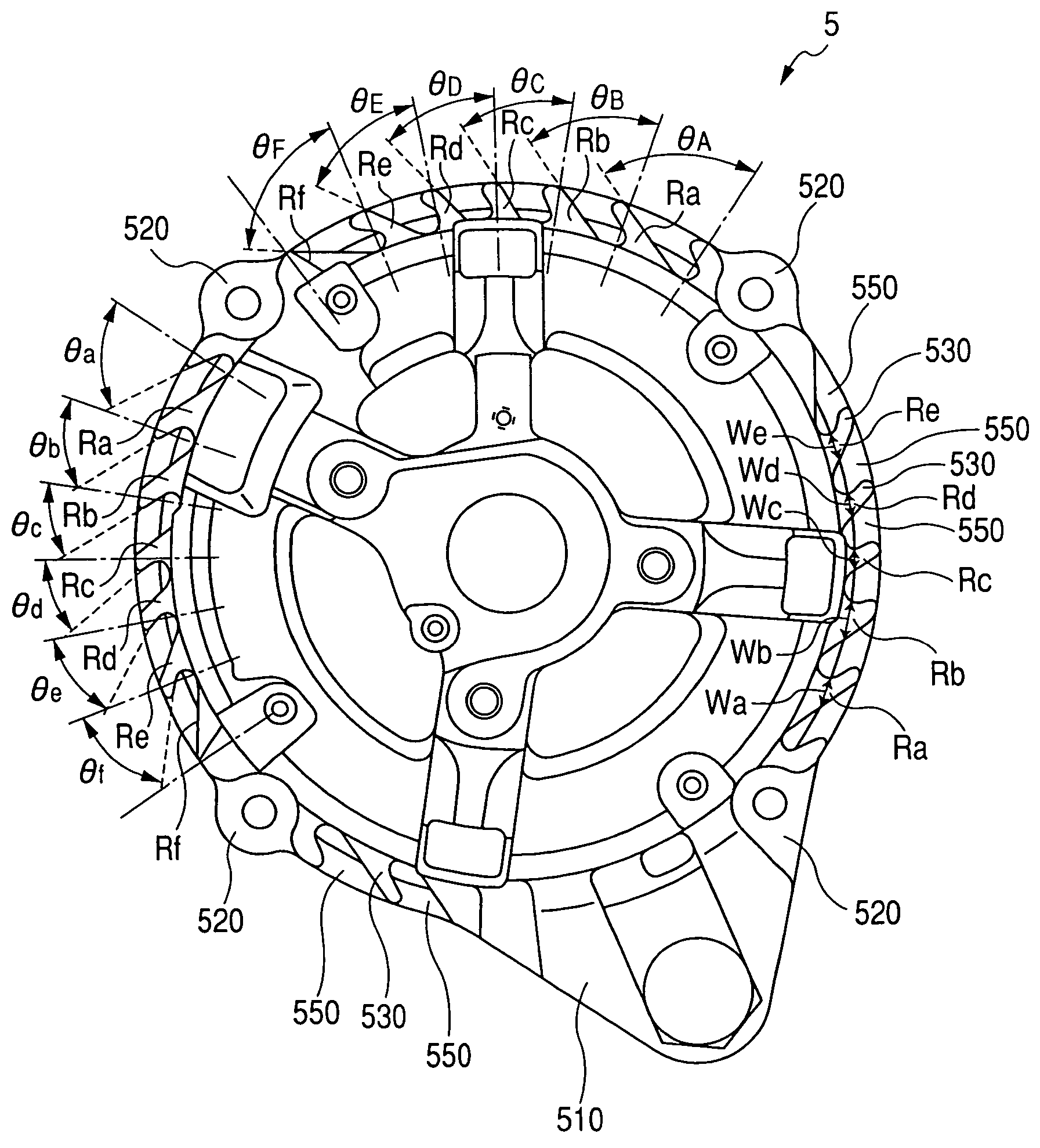
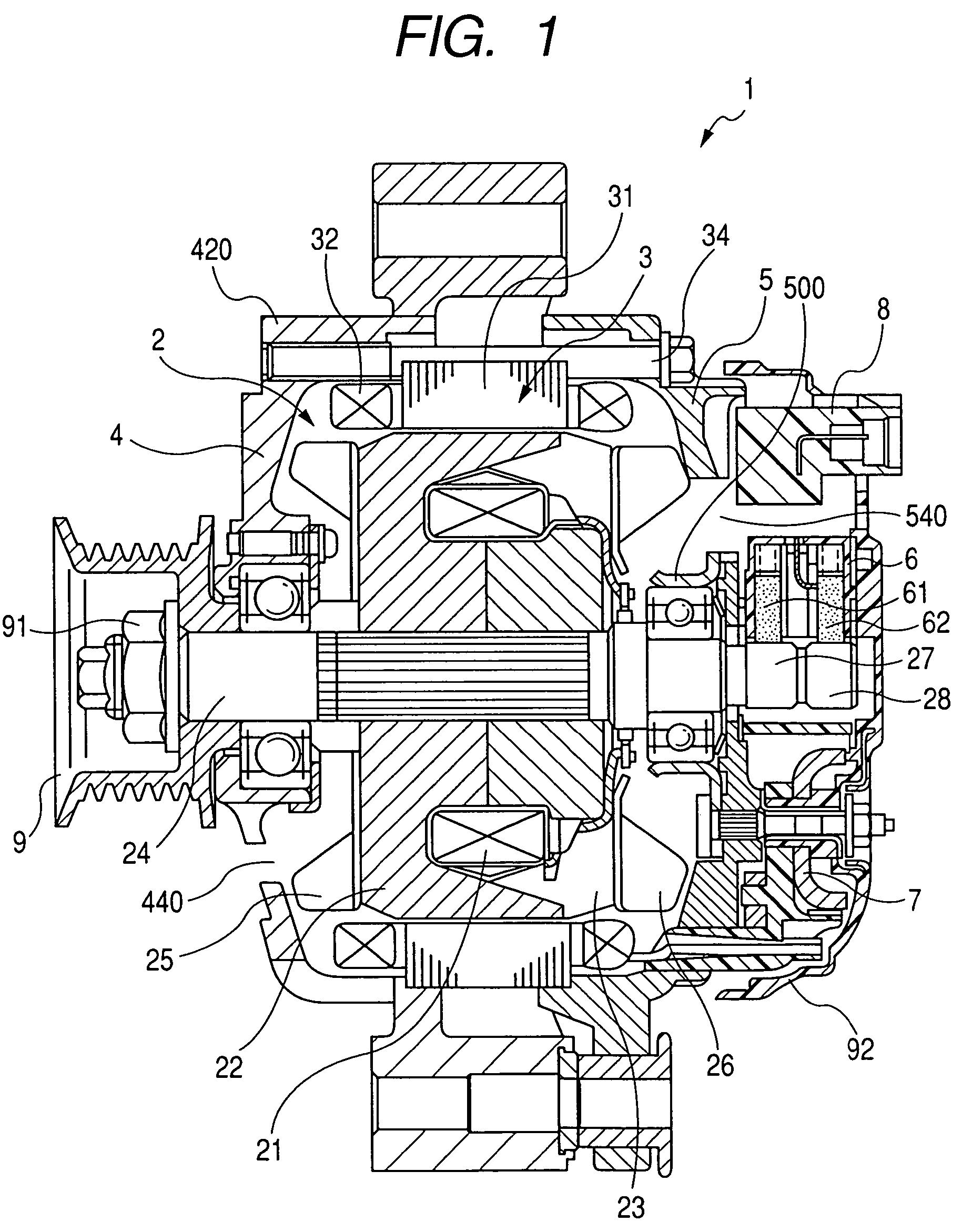
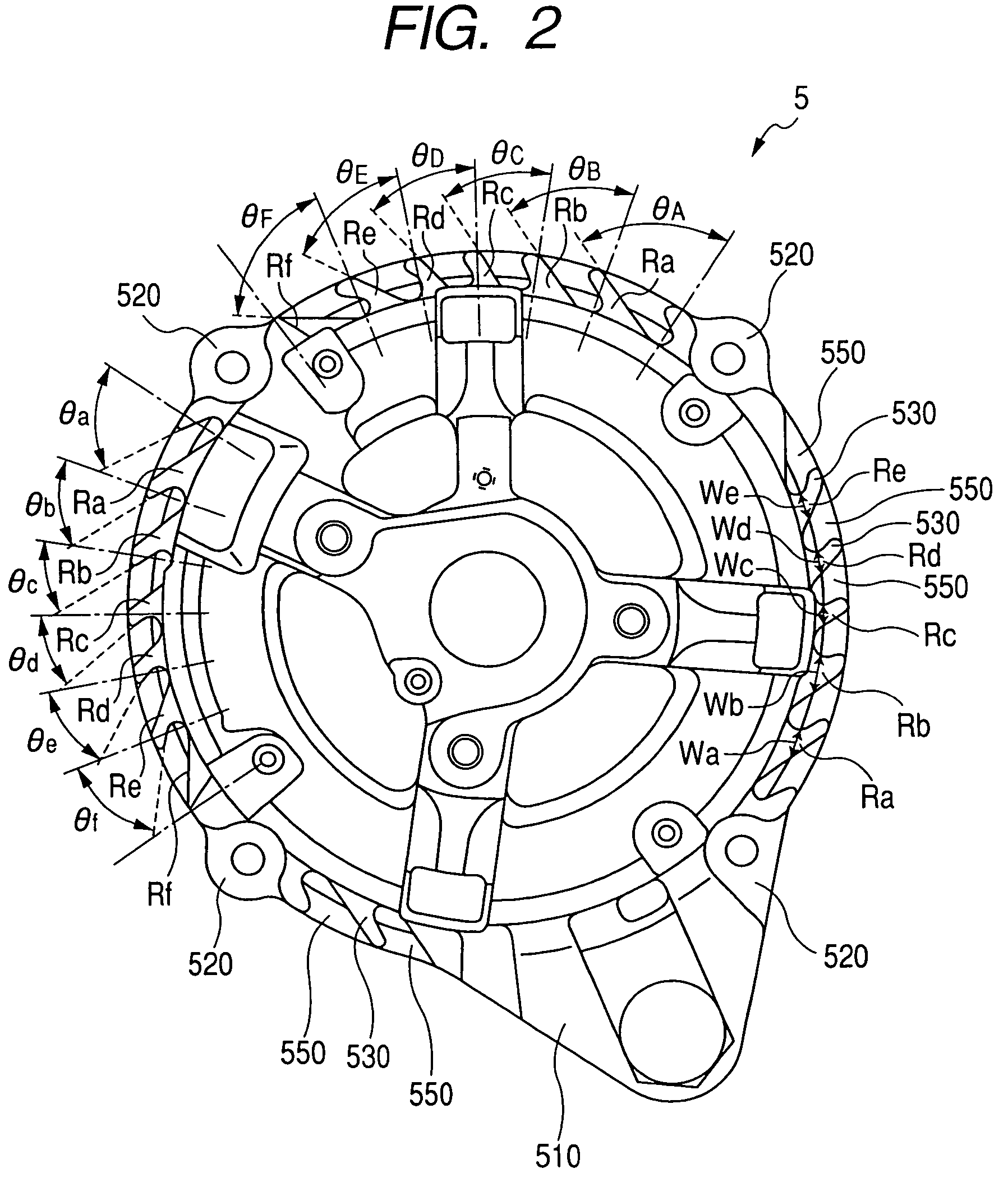
[0023]FIG. 1 is a cross-sectional view of a vehicle-use alternator 1 according to an embodiment of the invention. As shown in this figure, the vehicle-use alternator (simply referred to as the alternator hereinafter) 1 includes a rotor 2, a stator 3, a front side housing 4, a rear side housing 5, a brush device 6, a rectifier 7, a voltage regulator 8, and a pulley 9.

[0024]The rotor 2 includes a front side field core 22 and a rear side field core 23 each mounted to a rotating shaft 24 and having six or eight claw portions, between which a field winding 21 made of a copper wire concentrically wound in a cylindrical shape is held. A cooling fan 25, which may be of the axial-flow type, or a mix of the axial-flow type and the centrifugal type, is fixed by welding to an end surface of the front side field core 22 in order to suck in cooling air from the front side and blows it in the axial direction and the radial direction. Likewise, a cooling fan 26 of the centrifugal type is fixed by w...


PUM


Abstract

The vehicle-use alternator includes a cooling fan rotating in one with a rotating shaft thereof to generate cooling air diffusing substantially in a radial direction of the rotating shaft, to thereby cool a stator thereof. A housing thereof rotatably supporting the rotating shaft and housing the rotor is provided with a plurality of supporting members circumferentially spaced on a periphery thereof to which the stator is secured, and a plurality of ribs formed on the periphery which are circumferentially arranged between the supporting members so as to form a plurality of cooling air discharge windows circumferentially arranged on the periphery. The ribs are inclined towards a downstream side with respect to a rotational direction of the rotor, and shaped that their inclination angles towards the downstream side between two adjacent ones of the supporting members reduce with increasing distance from a closer one of the two adjacent ones of the supporting members.

Description

CROSS-REFERENCE TO RELATED APPLICATION[0001]This application is related to Japanese Patent Application No. 2005-367318 filed on Dec. 21, 2005, the contents of which are hereby incorporated by reference.BACKGROUND OF THE INVENTION[0002]1. Field of the Invention[0003]The present invention relates to an alternator (AC generator) mounted on a vehicle such as a passenger car or a truck.[0004]2. Description of Related Art[0005]Recently, the engine noise of a vehicle such as a passenger car or a truck has been steadily reduced to meet the social demand for the reduction of vehicle noise, and also to increase merchantability of the vehicle. However, reducing the engine noise tends to make the noise of auxiliaries rotating at relatively high speeds which are mounted on the same vehicle, especially a vehicle-use alternator, more harsh and conspicuous.[0006]There have been proposed various techniques for reducing the noise of a vehicle-use alternator, while improving the self-cooling capabilit...

Claims


Application Information

Patent Timeline
Patent Type & Authority Patents(United States)
IPC IPC(8): H02K9/00H02K5/20H02K5/24H02K9/06
CPCF04D25/082H02K9/06H02K5/20H02K5/207F04D29/5806
Inventor AOSHIMA, TOSHIHISA
Owner DENSO CORP
Why Eureka
Try Eureka