Comparator circuit
a comparator circuit and circuit technology, applied in pulse manipulation, pulse technique, instruments, etc., can solve the problems of slow average voltage rise, long time to obtain binarized data, and average voltage vref cannot adapt to it quickly
- Summary
- Abstract
- Description
- Claims
- Application Information
AI Technical Summary
Problems solved by technology
Method used
Image
Examples
first embodiment
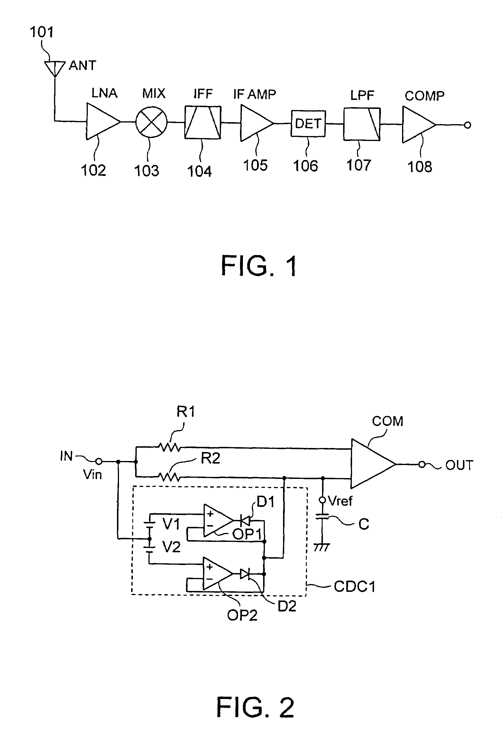
[0057]FIG. 2 shows the configuration of a comparator circuit in the first embodiment.
[0058]In the FM detection by the above FSK receiving circuit, the DC voltage of a detection output varies in proportion to the input frequency. Therefore, the DC voltage varies when there happens a change from a no-signal condition to a condition in which a signal is present, and the comparator circuit 108 is required to adapt to this change rapidly.
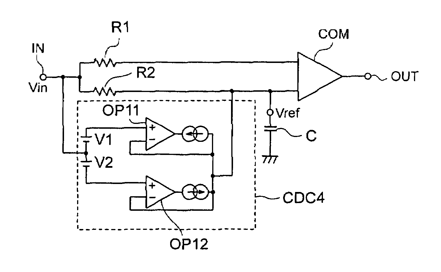
[0059]This comparator circuit 108 has a comparator COM whose first and second input terminals are connected to resistors R1 and R2 respectively, and an input signal voltage Vin is input to the first and second input terminals via an input terminal IN.
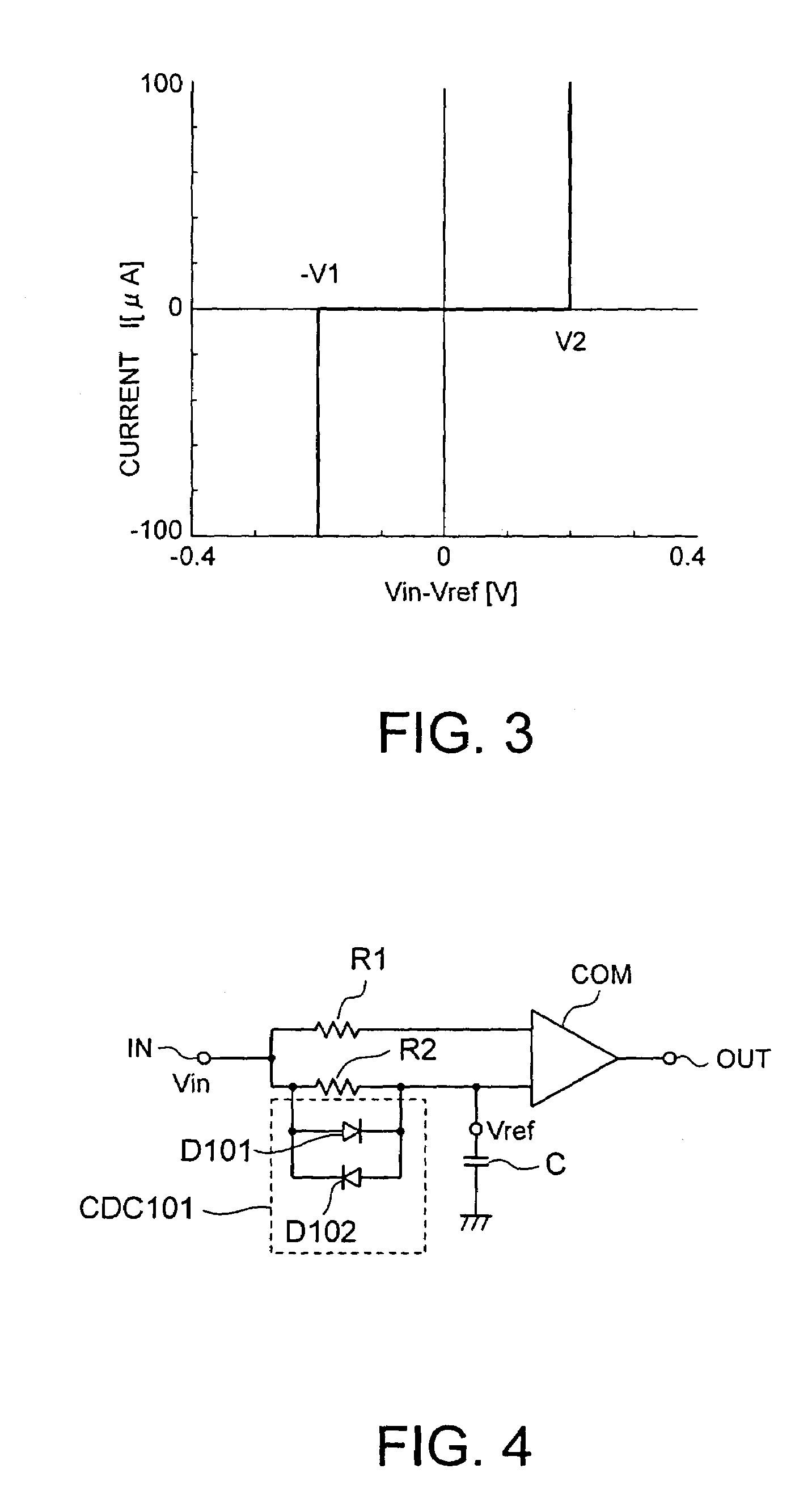
[0060]A capacitor C is connected between the second input terminal and a ground terminal. An average voltage Vref which is used for comparison is generated in the second input terminal by a low-pass filter including the resistor R2 and the capacitor C. A charge / discharge circuit CDC1 is provided to rapidly c...
second embodiment
[0081]A comparator circuit in the second embodiment will be described with reference to FIG. 6 showing the configuration of the comparator circuit.
[0082]The second embodiment differs from the above-described first embodiment in that a gain-variable type operational amplifier OP3 is connected in series between the input terminal IN, and the connection point of the resistors R1 and R2 in the first embodiment.
[0083]The level of an input signal voltage Vin1 input from the input terminal IN is changed by the gain-variable type operational amplifier OP3, and the input signal voltage Vin1 is output to the succeeding stage as an input signal Vin2.
[0084]According to the second embodiment, even in a case where an input signal voltage Vin1 given by the low-pass filter 107 in the preceding stage shown in FIG. 1 fluctuates and varies, an adjustment is made so that the relationship 2×V1 (or V2)=Vin2 (p-p) holds by changing the level by use of the gain-variable type operational amplifier OP3, ther...
third embodiment
[0098]The configuration of a comparator according to the third embodiment is shown in FIG. 11. In the above-described second embodiment, the level of the input signal voltage Vin is made variable, thereby an adjustment is made so that the relationship 2×V1 (or V2)=Vin2 (p-p) holds.
[0099]In contrast to this, in the third embodiment, the charge / discharge start voltage is made variable in the stage when the charge / discharge start voltage is input to the operational amplifiers OP1, OP2 in a charge / discharge circuit CDC3, thereby voltages V1a, V1b are adjusted as variable voltages so that the relationship 2×V1a (or V1b)=Vin2 (p-p) holds.
[0100]Other elements that are the same as in the above-described first embodiment are identified by the same reference numerals as in the first embodiment, and the descriptions of these elements are omitted.
PUM
 Abstract
Description
Claims
Application Information
 - R&D
- Intellectual Property
- Life Sciences
- Materials
- Tech Scout
- Unparalleled Data Quality
- Higher Quality Content
- 60% Fewer Hallucinations
Browse by: Latest US Patents, China's latest patents, Technical Efficacy Thesaurus, Application Domain, Technology Topic, Popular Technical Reports.
© 2025 PatSnap. All rights reserved.Legal|Privacy policy|Modern Slavery Act Transparency Statement|Sitemap|About US| Contact US: help@patsnap.com


