DC motor rotation control apparatus

a technology of detecting apparatus and dc motor, which is applied in the direction of dc motor rotation control, dynamo-electric converter control, motor/generator/converter stopper, etc., can solve the problems of inability to detect the rotation of the rotary encoder, the inability to rotate the rotary encoder, etc., and the inability to use the rotary encoder. disadvantageous, space and cost increas

Inactive Publication Date: 2003-09-30
RICOH KK
View PDF17 Cites 37 Cited by
  • Summary
  • Abstract
  • Description
  • Claims
  • Application Information

AI Technical Summary

Benefits of technology

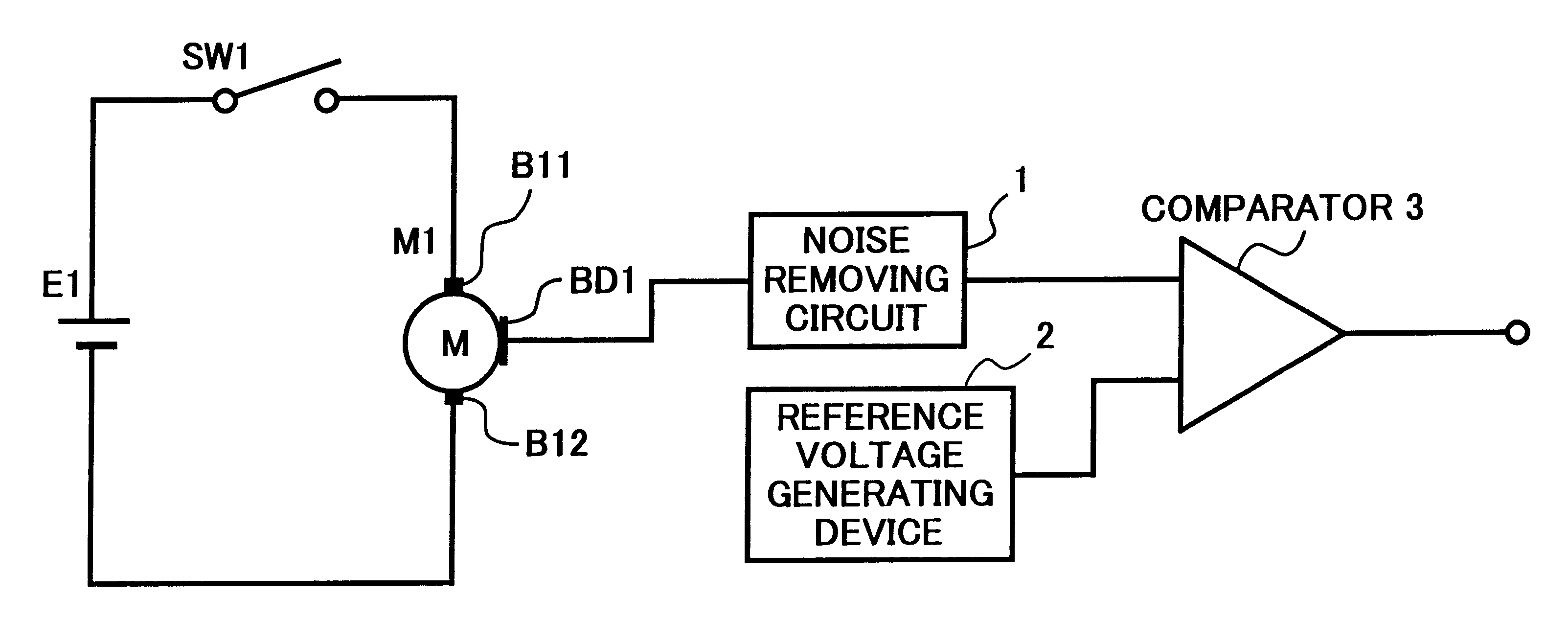
Accordingly, an object of the present invention is to provide a novel DC motor rotation detecting apparatus and a DC motor rotation control apparatus that can detect and control at least one of a rotation speed, a cumulative rotation number, a rotational position, and a rotational direction of a DC motor with accuracy.
These and other objects are achieved according to the present invention in a novel direct current motor rotation control apparatus, a method and device for controlling a rotational speed of a direct current motor, and an apparatus having the direct current motor rotation control apparatus. The apparatus and device control rotational operations of a direct current motor such that the direct current motor rotation control apparatus includes at least one rotation detecting brush which detects a signal indicative of an operation of the direct current motor, a motor driving circuit which drives the direct current motor by applying the direct current drive voltage to the pair of electrode brushes, a reference voltage generating device which generates a ref

Problems solved by technology

Although the rotary encoder method allows an accurate detection of the rotation of the motor, space and cost for the rotary encoder constructed by the rotation slit disk, the photointerrupter, etc. are ine

Method used


Image

  • DC motor rotation control apparatus
  • DC motor rotation control apparatus
  • DC motor rotation control apparatus

Examples


first embodiment

FIG. 10 illustrates a construction of a DC motor rotation control apparatus that controls the rotational operation of the DC motor according to the present invention. In the DC motor rotation control apparatus of FIG. 8, the output voltage of the drive power supply circuit E2 is constant, and the rotation of the DC motor M2 is controlled by the switching control of the motor driving circuit 5. On the other hand, an output voltage of a drive power supply circuit of FIG. 10 corresponding to the drive power supply circuit E2 of FIG. 8 is variable.

The DC motor rotation control apparatus illustrated in FIG. 10 includes an output variable power supply circuit 11, a motor driving circuit 12, a DC motor 13, a noise removing circuit 14, a reference voltage generating device 15, a reference voltage selecting device 16, a comparator 17, and a motor control circuit 18. The motor driving circuit 12, the DC motor 13, the noise removing circuit 14, the reference voltage generating device 15, the r...

second embodiment

Next, a DC motor rotation control apparatus that controls a rotational operation and a cumulative rotation number of the DC motor according to the present invention is described. The DC motor rotation control apparatus of FIG. 15 has a similar construction to the DC motor rotation control apparatus of FIG. 10 employing a motor control circuit 19 instead of the motor control circuit 18.

The motor control circuit 19 includes a microcomputer (not shown), a reference voltage selecting signal generating device 191, a motor control signal generating device 192, a pulse interval measuring device 193, a rotation speed calculating device 194, a pulse number counting device 195, a cumulative rotation number calculating device 196, a remaining rotation number calculating device 197, a rotation speed switching device 198, and a speed-voltage converting device 199.

Respective functions of the reference voltage selecting signal generating device 191, the motor control signal generating device 192, ...


PUM


Abstract

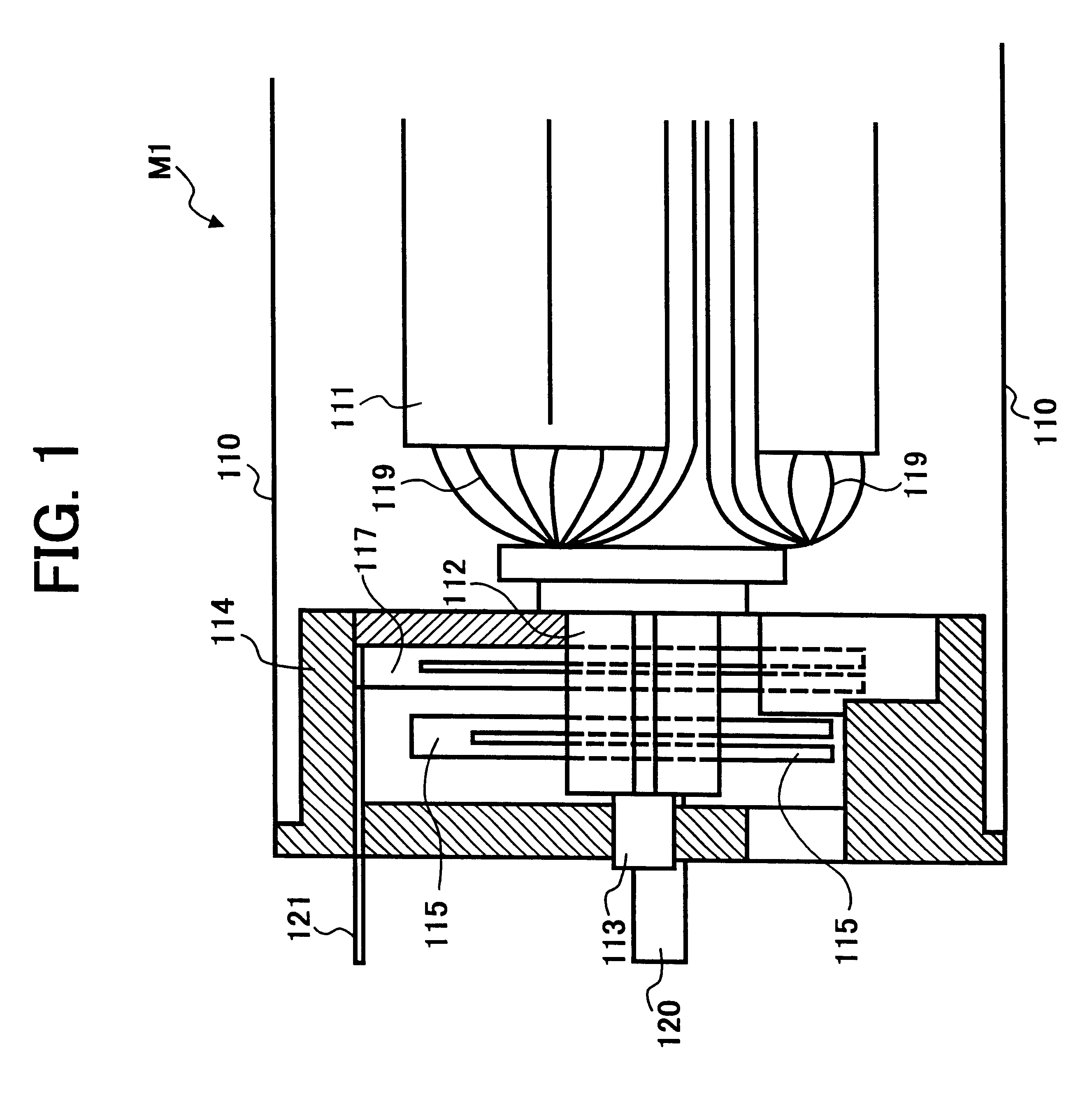
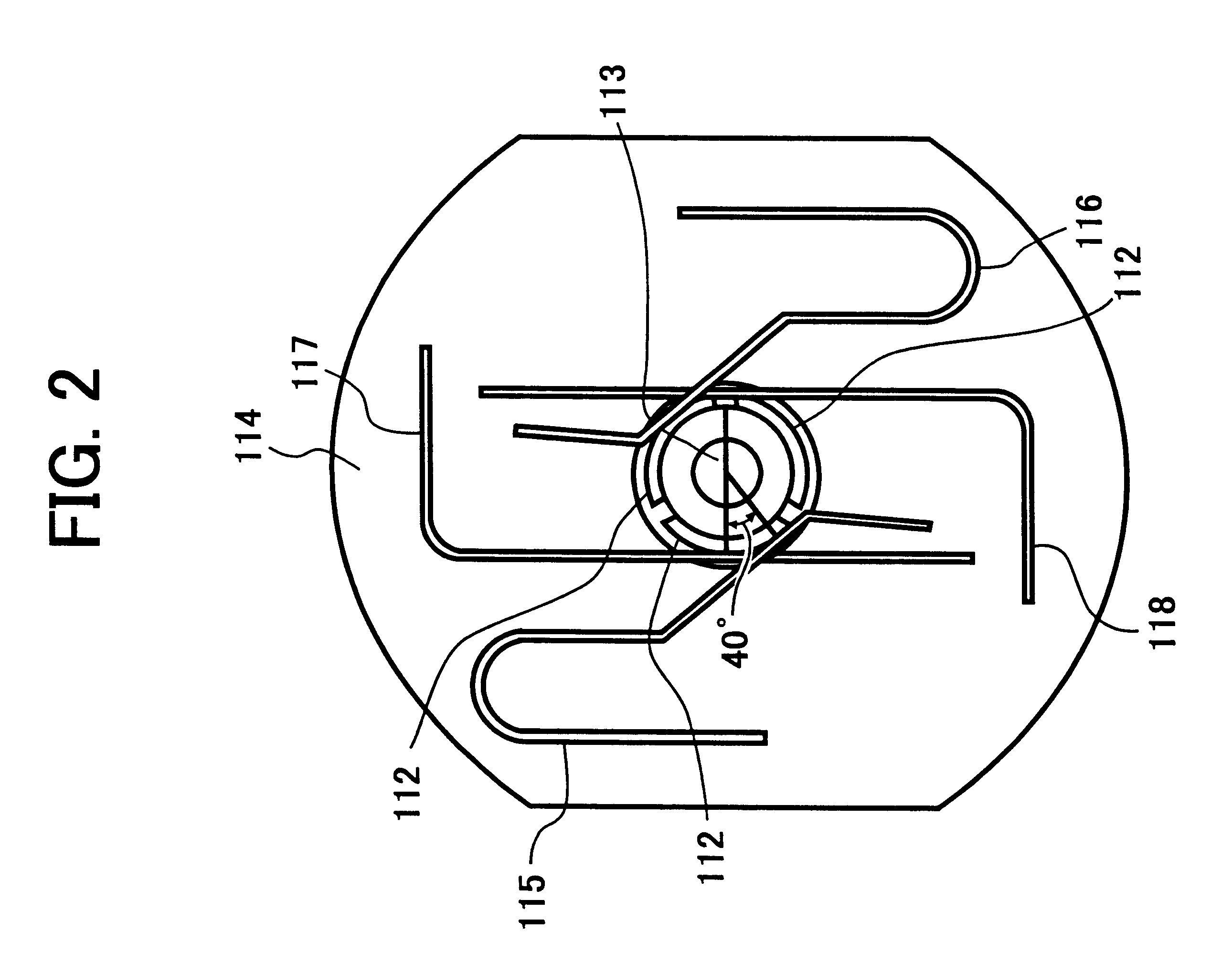
A direct current motor rotation control apparatus, a method and device for controlling a rotational speed of a direct current motor, and an apparatus having the direct current motor rotation control apparatus. The apparatus and device control rotational operations of a direct current motor such that the direct current motor rotation control apparatus includes at least one rotation detecting brush which detects a signal indicative of an operation of the direct current motor, a motor driving circuit which drives the direct current motor by applying the direct current drive voltage to the pair of electrode brushes, a reference voltage generating device which generates a reference voltage a comparator which compares a voltage detected by the rotation detecting brush with the reference voltage generated by the reference voltage generating device and produces an output comparison voltage, and a motor control circuit which adjusts the direct current drive voltage based on the output comparison voltage. The direct current motor includes including a stator, a rotor with a rotation shaft and rotor coils, a commutator connected to the rotor coils, and a pair of electrode brushes in sliding contact with the commutator. The at least one rotation detecting brush contacts the commutator at a different axial position from an axial position contacted by the pair of electrode brushes. The comparator can compare a voltage detected by the rotation detecting brush with the reference voltage generated by the reference voltage generating device and produces as a comparison voltage output pulses of voltage. As such, the motor control circuit can determine an instantaneous rotational speed and adjust the drive voltage to the pair of electrode brushes accordingly.

Description

BACKGROUND OF THE INVENTION1. Field of the InventionThe present invention relates to an apparatus wherein a DC (direct current) motor is used as a driving force for performing mechanical operations, and stabilization of the rotation speed of the DC motor and control of cumulative rotation number of the DC motor are required, more particularly relates to a DC motor rotation detecting apparatus and a DC motor rotation control apparatus wherein rotational operations of a rotor of the DC motor are controlled by detecting at least one of a rotational direction, a rotation speed, a cumulative rotation number, and a rotational position of the rotor.2. Discussion of the BackgroundA brush-use DC motor is much used as a driving force for mechanical operations in a camera, such as, for example, zooming operations wherein photographic lenses including a zoom lens are zoomed, focusing operations wherein at least one of a photographic lens and an imaging device is moved along an optic axis of the...

Claims


Application Information

Patent Timeline
IPC IPC(8): H02P1/18H02K23/66H02P7/00H02P7/18H02P7/28
CPCH02K23/66H02P1/18H02P7/0044H02P7/28H02P7/0094H02P7/04
Inventor OHNO, YOSHIMITSURUKAWA, IKUYAKOYAMA, KENJI
Owner RICOH KK
Why Eureka
Try Eureka