Chip pin open circuit and short circuit tester and method therefor

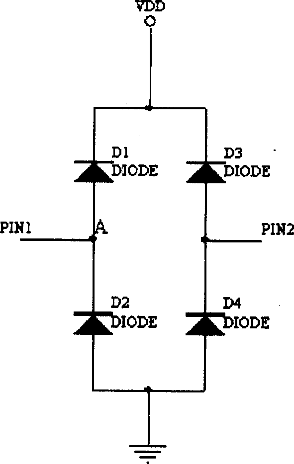
A short-circuit test and chip tube technology, which is used in semiconductor/solid-state device test/measurement, single semiconductor device test, measurement of electricity, etc., can solve the problem of high price, complex structure of test equipment, and inability to test the open circuit of diode D2 connected in reverse series. or short circuit, etc., to achieve the effect of low cost and simple structure

Inactive Publication Date: 2005-06-29
ASE ASSEMBLY & TEST SHANGHAI
View PDF0 Cites 34 Cited by
  • Summary
  • Abstract
  • Description
  • Claims
  • Application Information

AI Technical Summary

Problems solved by technology

At present, the equipment for the above test can only test whether the diode D1 connected in series in the forward direction is open or short circuited, and cannot test the open circuit or short circuit of the diode D2 connected in series in the reverse direction.
Moreover, this test equipment is complex in structure and expensive

Method used


Image

  • Chip pin open circuit and short circuit tester and method therefor
  • Chip pin open circuit and short circuit tester and method therefor
  • Chip pin open circuit and short circuit tester and method therefor

Examples


Embodiment Construction

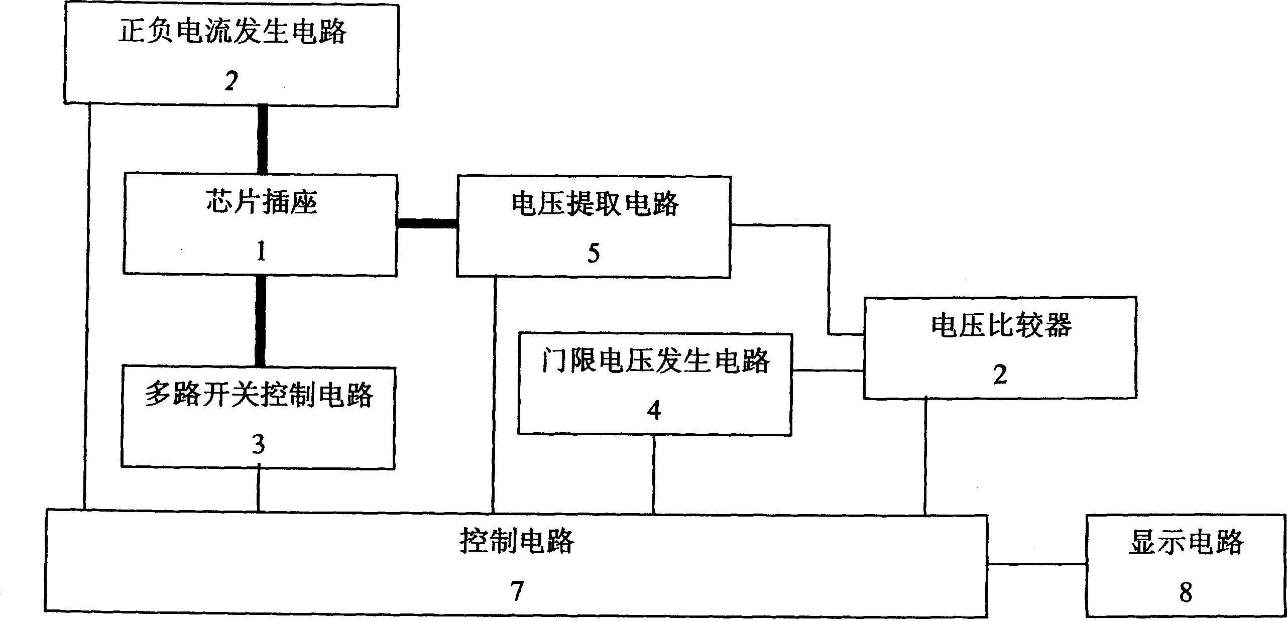
[0040] see figure 2 , figure 2 The chip pin open / short test machine of the present invention is shown. As can be seen from the structure diagram, the testing machine includes: chip socket 1, positive and negative current generation circuit 2, multi-way switch control circuit 3, threshold voltage generation circuit 4, voltage extraction circuit 5, voltage comparator 6, control circuit 7 and display circuit 8.

[0041] The chip socket 1 can be used to insert the chip to be tested, and the socket 1 can be designed as a universal type to adapt to chips with different numbers of pins.

[0042] The positive and negative current generating circuit 2 is used to generate positive current or negative current, which provides either positive current or negative current at the same time, that is to say, at the same time, the positive and negative current generating circuit 2 only provides current in one direction . The current generated by the positive and negative current generating...


PUM


Abstract

This invention relates to chip pin switch or short circuit test machine, which comprise the following: chip socket; positive or negative current generator circuit to provide positive or negative current to the chip pin; multi-path switch control circuit to control the rest chip pin ground connection; voltage extraction circuit to extract the output voltage from the chip pin; threshold voltage generation circuit to generate positive or negative threshold voltage; voltage comparer to compare the pin output voltage and threshold voltage and to output comparison results; control circuit to whole control the above circuit; display device to receive the signals of the above control circuit and to display the output signals.

Description

technical field [0001] The invention relates to a testing machine and a testing method, in particular to a device and a method for testing whether chip pins are open or short circuited. Background technique [0002] Most of the pins of the integrated circuit chip have two protection diodes connected to the power supply VDD and the ground G respectively. figure 1 shows the protection circuit of two chip pins PIN1 and PIN2, figure 1 The internal circuit of the chip is omitted. Such as figure 1 As shown, a diode D1 is forwardly connected in series between the pin PIN1 and the positive power supply VDD, and a diode D2 is reversely connected in series between the pin PIN1 and the ground G. Similarly, a diode D3 is forwardly connected in series between the pin PIN2 and the positive power supply VDD, and a diode D4 is reversely connected in series between the pin PIN2 and the ground G. The function of this protection diode is to prevent the internal circuit of the chip from bei...

Claims


Application Information

Patent Timeline
Patent Type & Authority Applications(China)
IPC IPC(8): G01R31/02H01L21/66
Inventor 李维繁星
Owner ASE ASSEMBLY & TEST SHANGHAI
Why Eureka
Try Eureka