Closed-loop control charge pump circuit

A closed-loop control and control circuit technology, which is applied in the direction of conversion equipment without intermediate conversion to AC, can solve the problems of poor output power followability, etc., and achieve the effects of stable output voltage, small ripple, and reduced energy loss

Active Publication Date: 2010-03-10
GIGADEVICE SEMICON (BEIJING) INC
View PDF0 Cites 34 Cited by
  • Summary
  • Abstract
  • Description
  • Claims
  • Application Information

AI Technical Summary

Problems solved by technology

[0007] The object of the present invention is to solve the problem of the output power control of the charge pump, overcome the shortcomings of the poor output power followability of the existing charge pump circuit, keep the power supply capacity of the charge pump consistent with the actual driving capacity required by the load, and provide a charge pump that can dynamically adjust The output power of the charge pump control circuit

Method used


Image

  • Closed-loop control charge pump circuit
  • Closed-loop control charge pump circuit
  • Closed-loop control charge pump circuit

Examples


Embodiment Construction

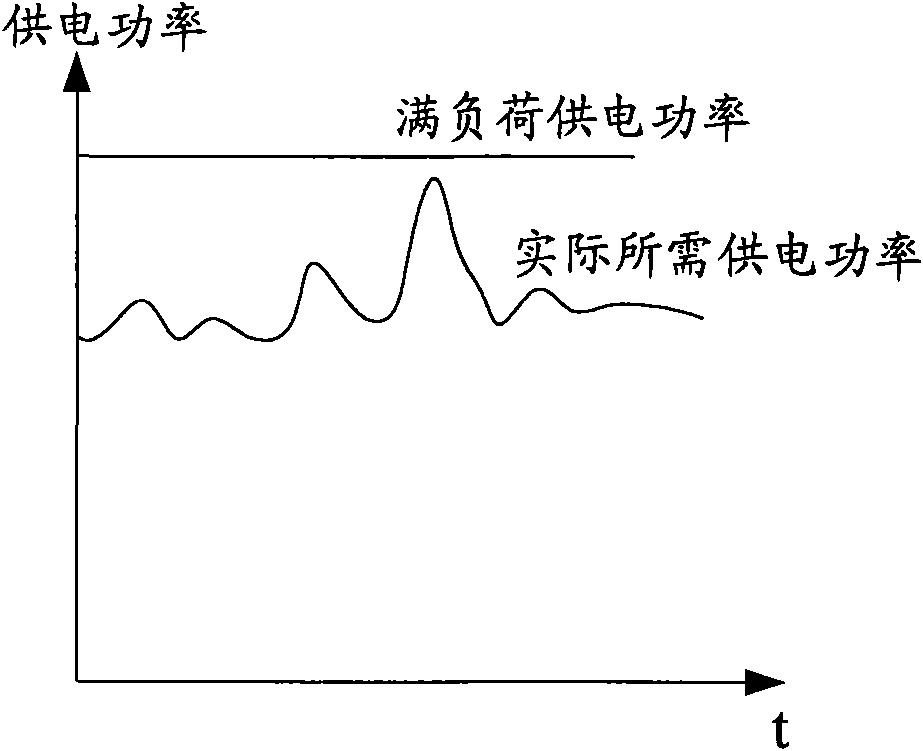
[0024] figure 2 It is a comparison chart of the full-load power supply of the charge pump circuit and the actual required power supply. It can be seen from the figure that the characteristic of the charge pump power supply is that the actual required power changes dynamically, and this change is usually random and irregular It is also difficult to predict. Moreover, in order to meet the peak demand, the full-load power supply capacity of the charge pump circuit is greater than the average value of the actual demand power supply. Therefore, the full-load power supply of the charge pump circuit will cause a great waste of electric energy.

[0025] image 3 It is a schematic diagram of the relationship between the power supply of the charge pump circuit and the oscillator frequency. Within the normal operating range of the charge pump circuit, the power supply and the oscillator frequency are approximately proportional. The detailed analysis of various performance indicators of...


PUM


Abstract

The invention relates to a closed-loop control charge pump circuit, which comprises a basic charge pump circuit and a control loop. The control loop comprises the following circuits which are connected in turn: a sampling circuit, a comparer, an oscillation control circuit, and an oscillator, wherein the sampling circuit is connected with a voltage output end (Vout) of a basic charge pump, and isused for sampling the voltage value of the Vout and generating a sampling voltage value V1 corresponding to the voltage value of the Vout according to a predefined function mapping relation f; the comparer is used for comparing the voltage value V1 with a preset reference voltage Vref and outputting the comparison result V2; the oscillation control circuit receives the comparison result V2 and generates a control signal Ctr1 according to the V2 value; and the oscillation frequency of the oscillator is controlled by the control signal Ctr1 to change continuously, and the oscillator outputs theoscillation frequency as the working frequency of the basic charge pump. Thus, the frequency of the oscillator of the charge pump circuit can be adjusted continuously and dynamically, and the whole charge pump circuit has good power following characteristics and reduces the energy consumption.

Description

technical field [0001] The invention relates to a power conversion circuit, in particular to a closed-loop control charge pump circuit for boosting voltage. Background technique [0002] A power supply is an essential part of a portable electronic device, and usually a battery is the main form of power supply for the portable electronic device. However, with the development of technology, the components in the equipment are becoming more and more diverse, and the requirements of various components for the power supply voltage are often different. Therefore, the battery alone cannot meet the power supply requirements, which requires a power converter to provide various voltages. different output voltage or current. The charge pump circuit is one of the most widely used forms of power converters, especially for boosting the supply voltage. For example, charge pump circuits are widely used in EPROM or flash memory (Flash) writing / erasing systems, liquid crystal display (LCD) ...

Claims


Application Information

Patent Timeline
Patent Type & Authority Applications(China)
IPC IPC(8): H02M3/07
Inventor 刘铭
Owner GIGADEVICE SEMICON (BEIJING) INC
Why Eureka
Try Eureka