Amplifier for multi-use of single environmental sensor

an environmental sensor and amplifier technology, applied in the field of electric circuits, can solve the problems of unreliable or unpredictable operation, signal rounded to levels too coarse to be of use, and insufficient measurement accuracy over a range of, say, 0 to 500 ppm, and achieve the effect of maintaining measurement accuracy

Active Publication Date: 2009-12-15
JOHNSON CONTROLS TYCO IP HLDG LLP
View PDF15 Cites 4 Cited by
  • Summary
  • Abstract
  • Description
  • Claims
  • Application Information

AI Technical Summary

Benefits of technology

[0009]In this way, the gain of the electrical circuit is greater when current is flowing only through the first branch of the feedback loop. The gain of the electrical circuit reduces when current begins to flow through the second branch of the feedback loop. The gain reduces gradually because the current flowing through the first branch is prevented from decreasing when the second branch is switched into the feedback loop. A non-linear response to the input signal is achieved having a well defined knee point, the knee point being where the input current reaches the predetermined value. The electrical circuit is more sensitive to signals below the knee point and less sensitive to signals above the knee point.
[0012]In a preferred embodiment, the switching means is a transistor. In this way, the predetermined value may be altered by changing the bias voltage of the transistor. Preferably, the transistor operates in a cut-off mode when the input signal is below the predetermined value. Preferably, the transistor operates in an active mode when the input signal is equal to or greater than the predetermined value. In this way, the transistor is not saturated and the current flowing through it is controlled by the bias voltage and the relative value of the resistive branch. The transistor is preferably a bipolar junction transistor, and is more preferably a pnp bipolar junction transistor. Preferably, the collector terminal of the transistor is connected to the input of the amplifier and the emitter terminal is connected to a resistive element which is in turn connected to the output of the amplifier. Preferably, the collector terminal is connected to a feedback node, where a portion, at least, of the output of an amplifier is fed back to the input of the amplifier. In this way, a sharp transition is achieved at the knee point. Preferably, means for applying a bias voltage to the base of the transistor is provided. In this way, the predetermined value of the circuit can be adjusted. Preferably, the transistor is such as to switch from a cut-off mode to an active mode when the voltage at the emitter terminal reaches a value equal to the bias voltage plus the transistor switch-on voltage. The arrangement may be such that the voltage at the emitter of the transistor is controlled to compensate for variations of the transistor switch-on voltage with temperature. Alternatively, the arrangement may be such that the bias voltage of the transistor is controlled to compensate for variations of the transistor switch-on voltage with temperature. In this way, measurement accuracy is maintained with changing temperature.

Problems solved by technology

However, by simply replacing two sensors and their respective detectors with a single sensor and detector, accuracy of measurement over a range of, say, 0 to 500 PPM may not be sufficiently accurate.
For example, when low output levels are sent from a detector to an analogue-to-digital converter (ADC) or comparator having a limited resolution, the quantisation effect could result in the signal being rounded to levels that are too coarse to be of use.
However, these devices have undesirable characteristics that result in unreliable or unpredictable operation, including temperature dependency, leakage current, noise and tolerance.
This is not an ideal solution to the problem due to factors such as component cost, component count and power consumption.

Method used


Image

  • Amplifier for multi-use of single environmental sensor
  • Amplifier for multi-use of single environmental sensor
  • Amplifier for multi-use of single environmental sensor

Examples


Embodiment Construction

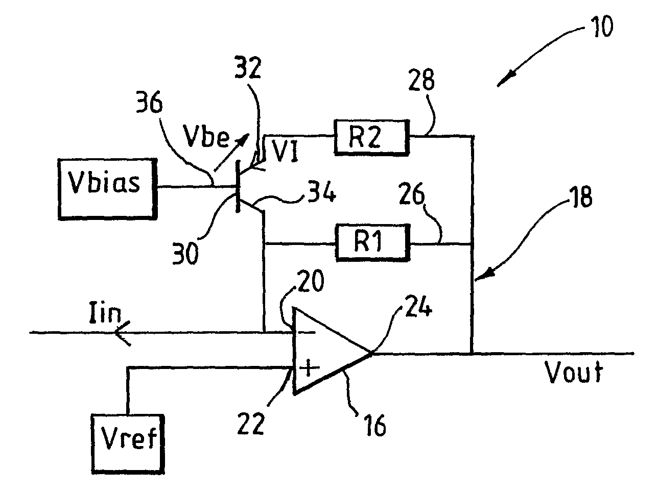
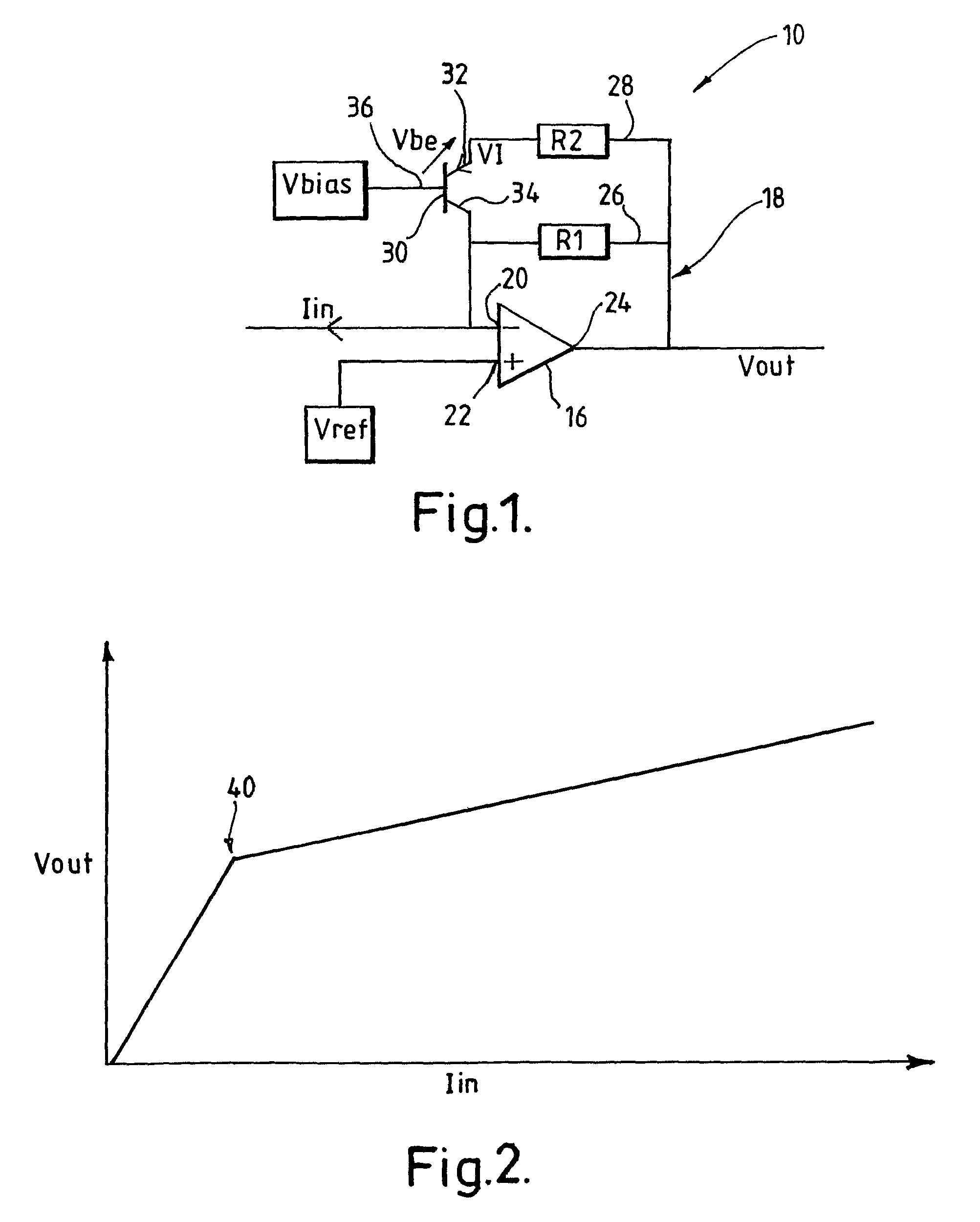
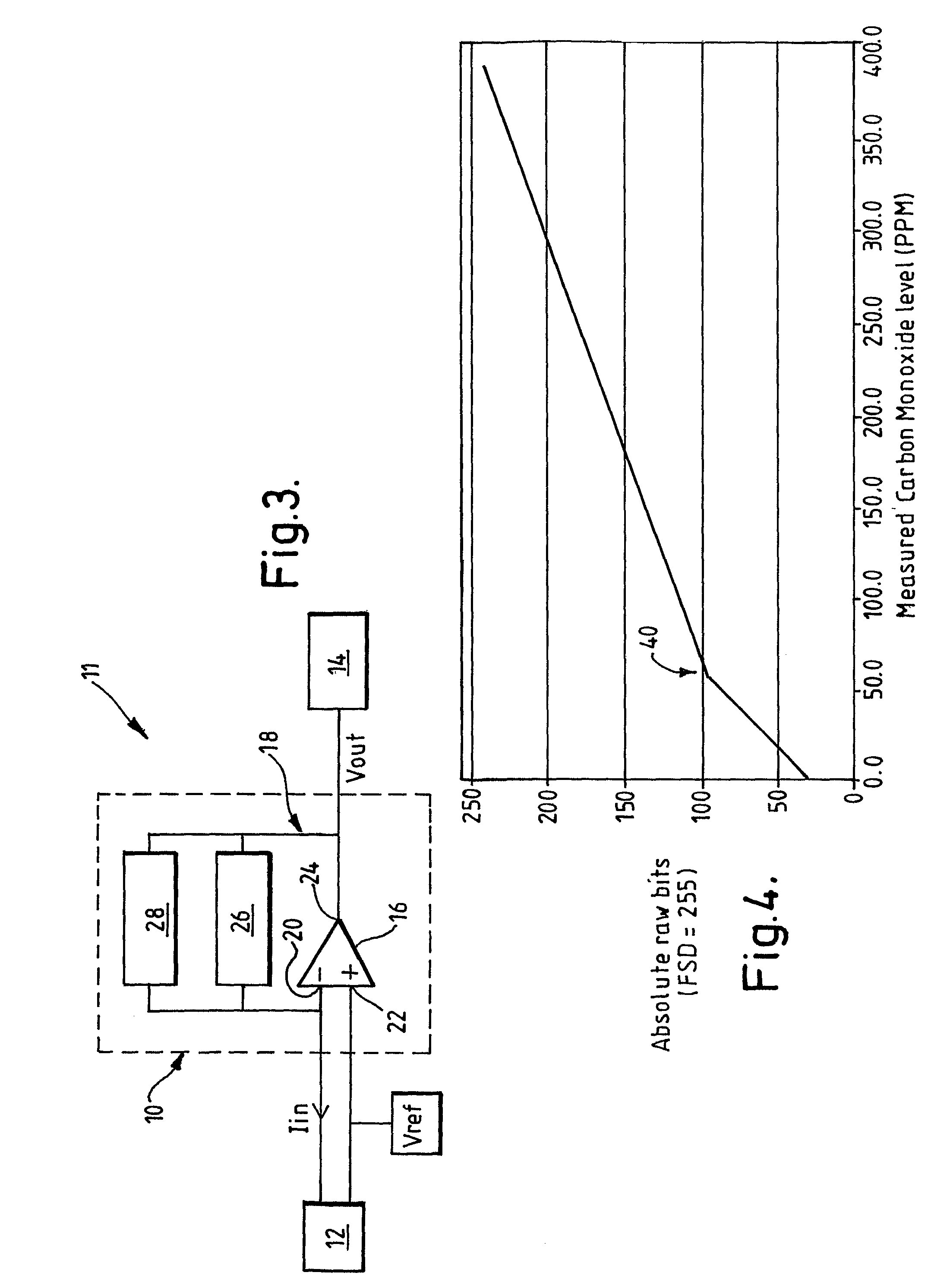
[0024]With reference to FIGS. 1 and 3, an electrical circuit 10 is provided which has a non-linear response to an input signal, Iin. For example, in a building management safety system, the circuit 10 can be used in a detection circuit 11 with a single detection element 12 to monitor carbon monoxide (CO) levels and an analogue-to-digital converter (ADC) 14 to convert the output into an appropriate form. The detection circuit 11 is used within the building management safety system to indicate the presence of a fire and / or the presence of a toxic level of carbon monoxide.

[0025]The circuit 10 comprises an operational amplifier (op-amp) 16 having a feedback loop 18. The operational amplifier 16 has an inverting input 20, a non-inverting input 22 and an output 24. The detection element 12 is connected to the inverting input 20 of the operational amplifier 16 and provides an input signal current, Iin. The operational amplifier 16 provides an output voltage, Vout, which is connected to the...


PUM

PropertyMeasurementUnit
bias voltageaaaaaaaaaa
voltageaaaaaaaaaa
temperatureaaaaaaaaaa

Abstract

A detection system in which a single sensor is employed to detect an extensive range of a parameter. The output signal from the sensor is fed to the input of the electrical circuit, having a feedback loop, wherein the electrical circuit has a non-linear transfer characteristic. The non-linear transfer characteristic is achieved by changing the behavior of the feedback loop of the electrical circuit at a predetermined level of input signal. The output of the circuit has a proportional relationship with the input until the input signal reaches this predetermined value, whereupon the behaviors of the feedback loop changes and the relationship of the output to the input of the circuit changes. While the input signal is above the predetermined value, the output of the circuit has a linear but disproportionate relationship with the input at a gradient different to that when the input signal is below the predetermined value. Further, the behavior of the feedback loop changes to create a knee point in the response between the proportional and the linear parts of the characteristic. In this way, an overall non-linear transfer characteristic is produced by the electrical circuit, the transfer characteristic having with a well-defined knee point. The resolution of input signals below the knee point may be greater than the resolution of signals above the knee point.

Description

RELATED APPLICATION[0001]This application claims the benefit of the prior foreign application GB 0506989.3, filed Apr. 6, 2005. The entire teachings of the above application are incorporated herein by reference.BACKGROUND OF THE INVENTION[0002]The present invention relates to an electrical circuit, and more particularly a non-linear transimpedance amplifier for use in a detection system. The present invention also relates to a method of changing the gain of an electrical circuit.[0003]The existence of a fire, for example, may be detected by various means, and it is known to employ a plurality of sensing elements that are responsive to different parameters. One such sensing element may be a carbon monoxide gas detector. In some installations there is a requirement also to detect toxic gases, of which carbon monoxide may be one. Conventionally, separate fire and gas detection circuits are installed each having, for example, its own carbon monoxide sensing element. The fire and gas det...

Claims


Application Information

Patent Timeline
Patent Type & Authority Patents(United States)
IPC IPC(8): G08B29/00G01N9/00H03K5/00H03F1/30H03F1/34H03F3/45
CPCH03F1/302H03F1/34H03F3/45475H03F2203/45524H03F2203/45136
Inventor BENNETT, STEVEN IAN
Owner JOHNSON CONTROLS TYCO IP HLDG LLP
Why Eureka
Try Eureka