
Method for detecting and documenting traffic violations at a traffic light

a technology for traffic lights and traffic violations, applied in the field of monitoring traffic areas, can solve the problems of high installation costs, surface association, and recording of pictures of vehicles

Active Publication Date: 2009-12-15
JENOPTIK ROBOT GMBH
View PDF20 Cites 23 Cited by
  • Summary
  • Abstract
  • Description
  • Claims
  • Application Information

AI Technical Summary

Benefits of technology

Enables the detection of red-light and speeding violations across multiple lanes with a single system, reducing costs and improving accuracy by predicting vehicle crossings and triggering images only when violations occur during specific traffic phases.

Problems solved by technology

Sensors that are embedded beneath the roadway surface are associated with high installation costs and must be replaced from time to time as the roadway surface wears down over time.
However, this solution would have the drawback that a picture of a vehicle is recorded even if the vehicle comes to a stop before the stop line.
Another drawback of a method according to EP 1 662 272 A1 is that in order to detect traffic violations, each lane requires a radar antenna and, moreover, each radar antenna must be oriented separately.
The investment cost for the traffic areas to be monitored increases with the number of the lanes to be monitored.

Method used


Image

  • Method for detecting and documenting traffic violations at a traffic light
  • Method for detecting and documenting traffic violations at a traffic light
  • Method for detecting and documenting traffic violations at a traffic light

Examples


Embodiment Construction

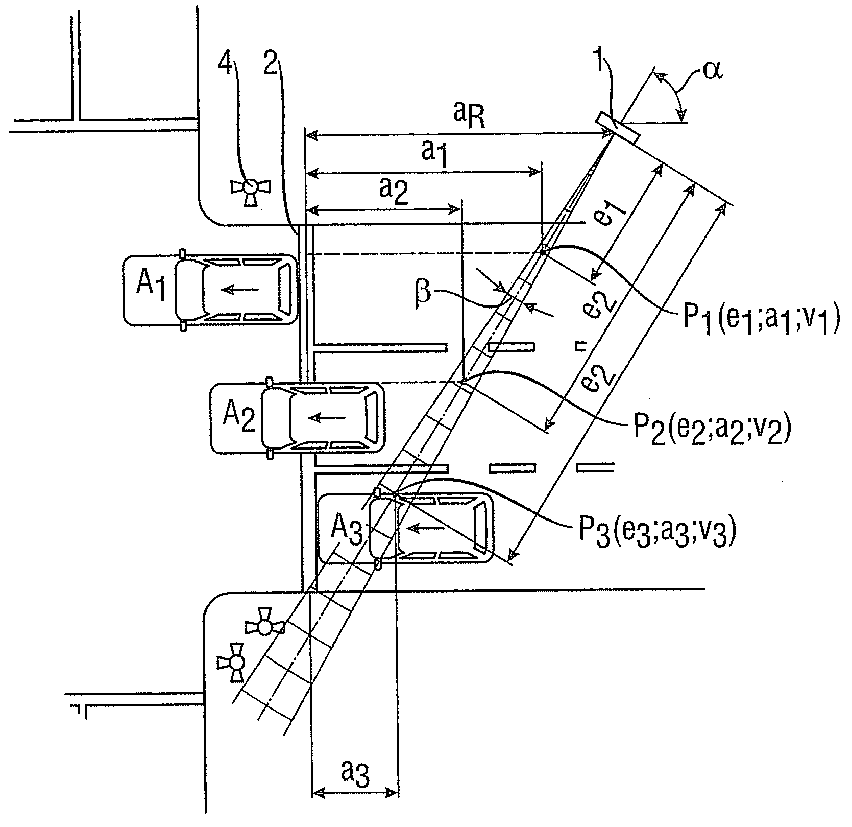
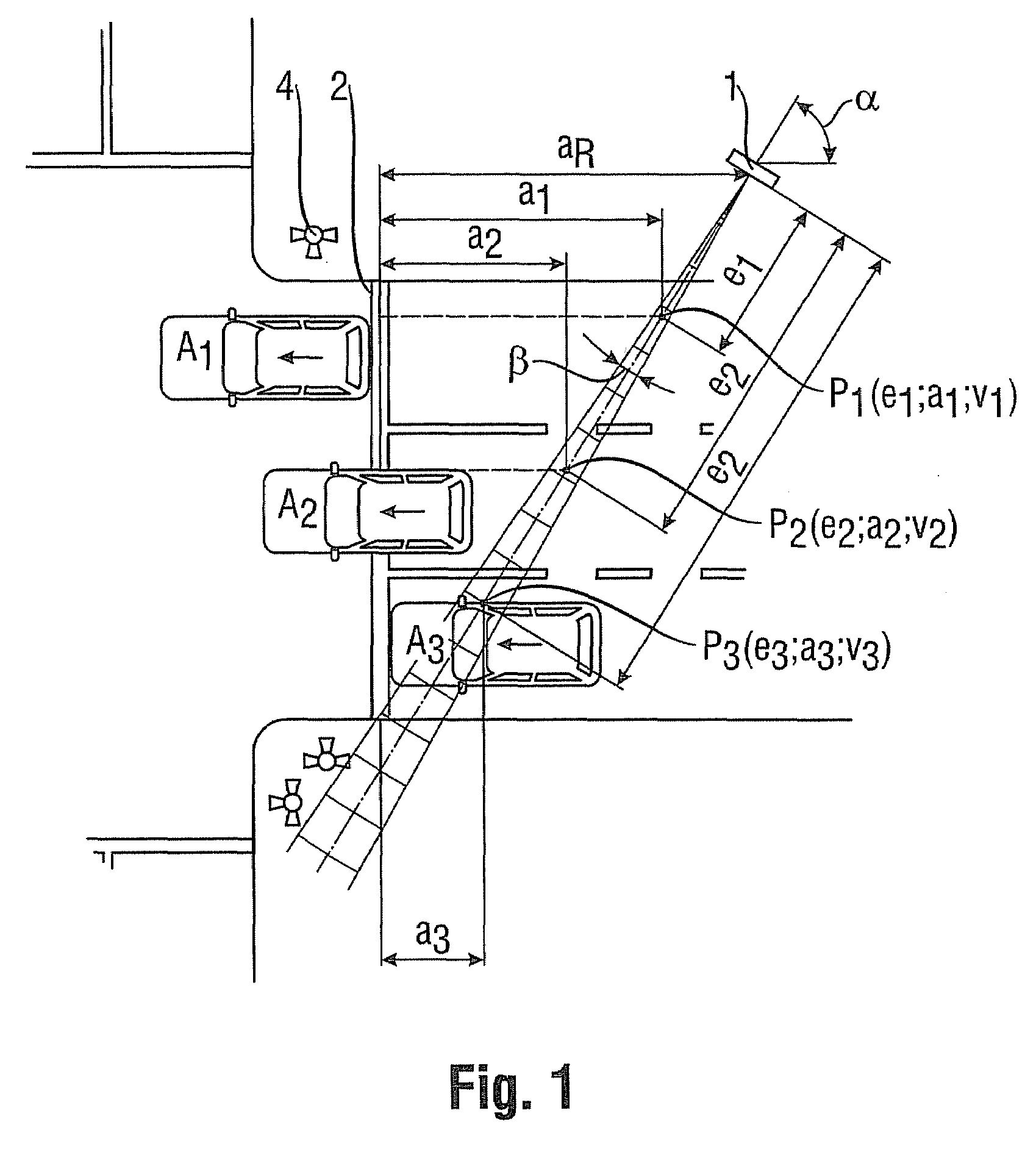
[0035]In a first practical example, shown in FIG. 1, the method will be carried out using a radar antenna of a radar device 1 which directs a narrow radar lobe with an angular aperture β smaller than 10°, in particular 5°, substantially diagonally with respect to the direction of the roadway, i.e., at a mounting angle α of approximately 60° with respect to the direction of the roadway across all three lanes of a roadway. As the vehicles pass through the radar lobe, they drive away from the radar device 1.

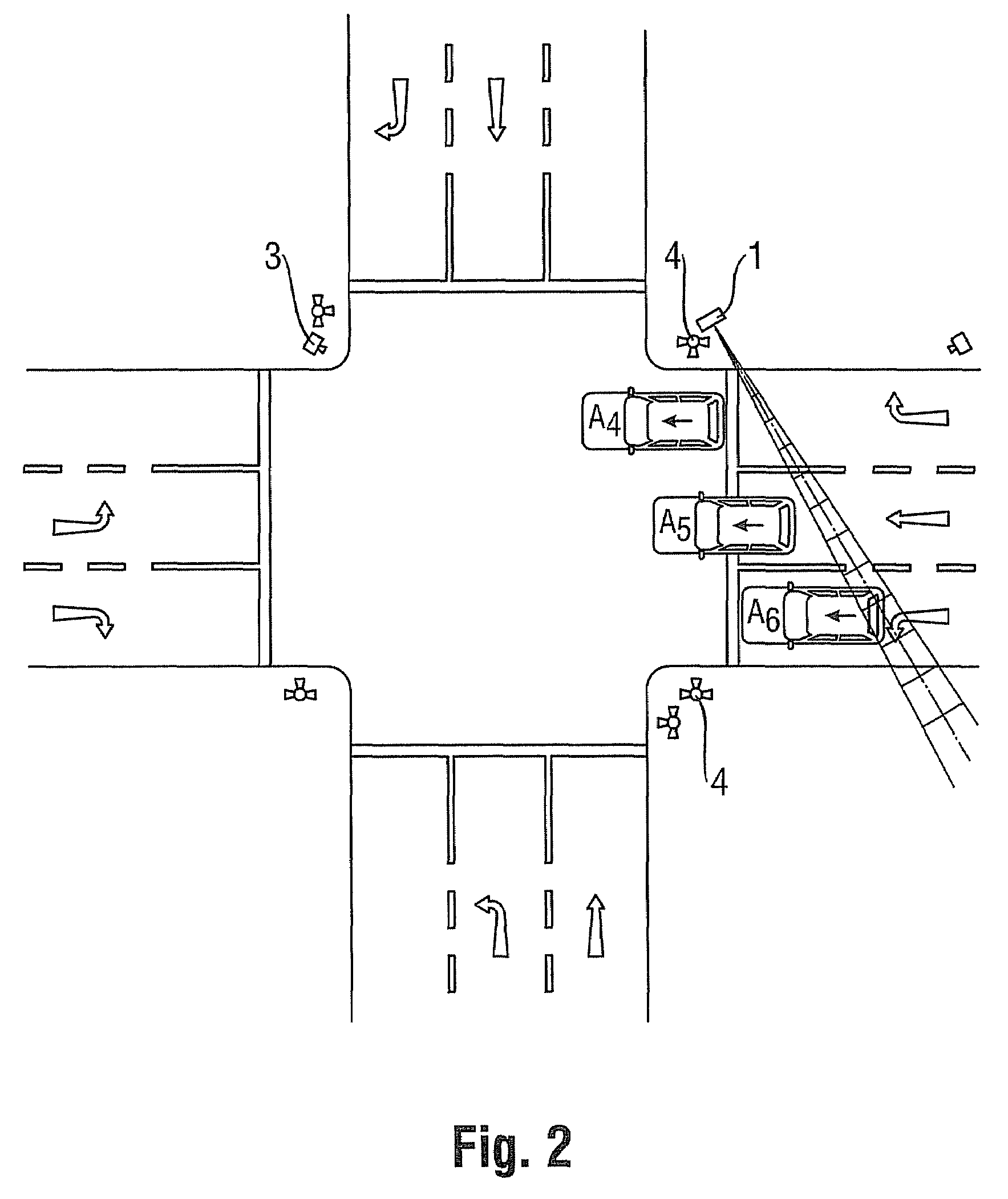
[0036]A second practical example, shown in FIG. 2, differs from the first practical example only in that the vehicles drive toward the radar device 1 as they pass through the radar lobe. This difference basically affects only the mounting site of a recording unit, by means of which a detected violation is documented by a captured image.

[0037]In the first practical example, the observation area is defined by the marginal rays of the radar lobe and the roadway boundaries on both sides...


PUM


Abstract

A method for detecting and documenting red-light violations and / or speeding violations in which a radar beam is directed across all lanes of a roadway of interest and in which the speed and the position of a vehicle which passes through the radar beam are determined from the radar signals so as to be able to predict the probability of a red-light violation from the speed and the determined distance of the measured vehicle from a stop line and to trigger the recording of images of the violating vehicle at predetermined distances from the stop line.

Description

FIELD OF THE INVENTION[0001]The present invention relates to a method for monitoring a traffic area (observation area) for the purpose of detecting traffic violations, as it is generically known from the European Patent Application EP 1 662 272 A1. Systems of this type can be used to establish a red-light violation, a speeding violation, and a combination of a red-light and speeding violation.BACKGROUND OF THE INVENTION[0002]In general, the known methods for monitoring traffic areas differ in that different types of sensors are used, which sensors are either embedded beneath the roadway surface or are disposed above the roadway surface. Sensors that are embedded beneath the roadway surface are associated with high installation costs and must be replaced from time to time as the roadway surface wears down over time.[0003]According to EP 1 662 272 A1, instead of embedding a sensor at a predetermined site in each individual lane, a radar beam of low beam expansion which is emitted by a...

Claims


Application Information

Patent Timeline
Patent Type & Authority Patents(United States)
IPC IPC(8): G01S13/62
CPCG01S13/42G01S13/585G08G1/0175G01S13/92G01S13/91
Inventor BEHRENS, ANDREASDOHMANN, BERNHARDTERLAU, NORBERT
Owner JENOPTIK ROBOT GMBH
Learn More