Integrated airborne substance collection and detection system

a detection system and airborne substance technology, applied in the field of airborne particulate collection and detection, can solve the problems of time-consuming process, inability to real-time threat assessment, and high cost and often efficient

Inactive Publication Date: 2009-12-15
MICROFLUIDIC SYST
View PDF75 Cites 55 Cited by
  • Summary
  • Abstract
  • Description
  • Claims
  • Application Information

AI Technical Summary

Problems solved by technology

This is a time-consuming process requiring various pieces of test equipment, which is impractical for real-time threat assessment.
Such processes also require the interaction of a human operator, which is costly and often efficient.

Method used


Image

  • Integrated airborne substance collection and detection system
  • Integrated airborne substance collection and detection system
  • Integrated airborne substance collection and detection system

Examples


third embodiment

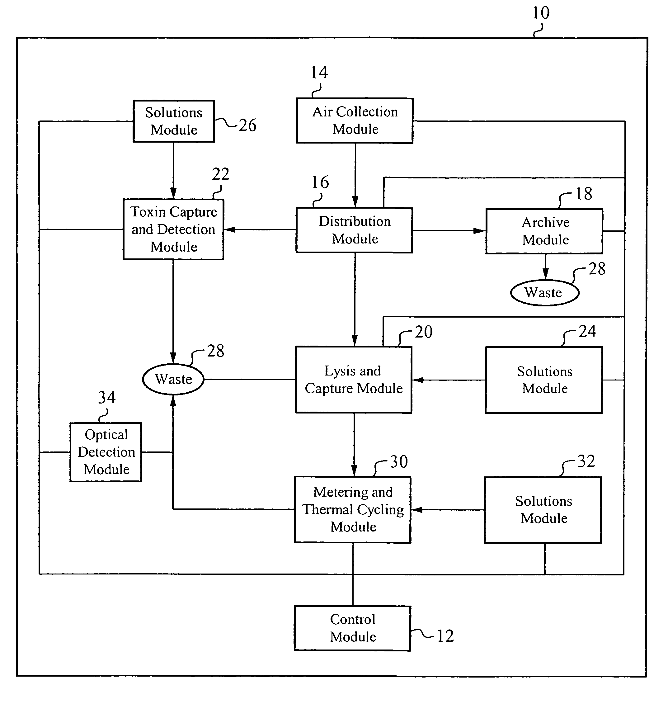
[0091]FIG. 12 illustrates an exemplary functional block diagram of the integrated collection and detection system. The integrated collection and detection system 600 includes the air collection module 510 and the confirmation device 520 of the collection and detection system 500, and the distribution module 16, the archive module 18, the lysis and capture module 20, the toxin capture and detection module 22, the solutions module 24, the solutions module 26, the waste module 28, the metering and thermal cycling module 30, the solutions module 32, and the optical detection module 34 of the collection and detection system 10. The collection and detection system 600 also includes a distribution module 610 and a control module 620. Each of the modules are fluidically coupled as appropriate to direct fluid sample and solutions within the collection and detection system 600.

[0092]Control of the collection and detection system 600 is maintained by the control module 620, which includes the ...

first embodiment

[0102]The network configuration described in relation to FIG. 1 includes the collection and detection system, the collection and detection system 10. It is understood that one, some, or all of the embodiments of the collection and detection system, for example the collection and detection system 10, the detection and collection system 500, and the collection and detection system 600, can be networked in a similar manner and in any combination.

[0103]The embodiments of the collection and detection system described above are for exemplary purposes. The microfluidic circuitry and module nature of the integrated collection and detection system provides flexibility and extensibility to interconnect and configure the modules, and associated sub-modular components, into any desired combination. Additionally, the specific configurations described for each of the modules is for exemplary purposes. The microfluidic circuitry and constituent components of each module can be adapted into any num...


PUM

PropertyMeasurementUnit
timeaaaaaaaaaa
optical characteristicsaaaaaaaaaa
interfaceaaaaaaaaaa

Abstract

A collection and detection system is configured as a detect to warn system in which the presence of specific types of particles are detected, and may or may not be identified. An air collection module intakes ambient air, detect the presence of one or more different types of airborne particles within the ambient air, and collect the airborne particles, such as within a fluid. A triggering mechanism is positioned to continuously monitor the airflow, to determine one or more characteristics of the airborne particles. If those measured characteristics match specific known characteristics, a trigger signal is generated. In response, a confirmation device performs a detection method on a fluid solution including the airflow particles to determine the presence of one or more different types of specific biological particles.

Description

GOVERNMENT LICENSE RIGHT[0001]This invention was made with Government support under Agreement No. W81XWH-04-9-0010 awarded by the Government. The Government has certain rights in this invention.CROSS-REFERENCE TO RELATED APPLICATIONS[0002]This patent application is related to commonly owned co-pending U.S. patent application Ser. No. 11 / 509,969, filed Aug. 24, 2006, entitled “An Integrated Airborne Substance Collection and Detection System”, and U.S. patent application Ser. No. 11 / 510,073, filed Aug. 24, 2006, entitled “An Integrated Airborne Substance Collection and Detection System”, which are hereby incorporated by reference in their entirety.FIELD OF THE INVENTION[0003]The invention relates to a method of and apparatus for collecting and analyzing particulates. More particularly, the invention relates to the collection and detection of airborne particulates.BACKGROUND OF THE INVENTION[0004]Bio-threat detectors are used to monitor the ambient air to detect the presence of potenti...

Claims


Application Information

Patent Timeline
Patent Type & Authority Patents(United States)
IPC IPC(8): G01N21/00
CPCG08B21/12G01N1/2273G01N2001/2217
Inventor NORTHRUP, ALLENPOURAHMADI, FARZADYUAN, BOBDEVITT, AMY J.
Owner MICROFLUIDIC SYST
Why Eureka
Try Eureka