Focus adjustable method of optical image

a technology of optical image and adjustable method, which is applied in the direction of camera focusing arrangement, printers, instruments, etc., can solve the problems of difficult to overcome the problem of generating uneven focus values, conventional focus adjustable method fails to discriminate whether the inherent imaging tolerance influences the focusing performance, and achieves enhanced optical image focusing performance

Inactive Publication Date: 2009-12-15
PRIMAX ELECTRONICS LTD
View PDF3 Cites 3 Cited by
  • Summary
  • Abstract
  • Description
  • Claims
  • Application Information

AI Technical Summary

Benefits of technology

[0008]It is an object of the present invention to provide a focus adjustable method of an optical image according to the tilt amount and the tilt direction of the lens module to perform two-dimensional focusing adjustment, so that the focusing performance of the optical image is enhanced.
[0010]A still object of the present invention provides a focus adjustable method of an optical image, which is capable evaluating the focusing performance.
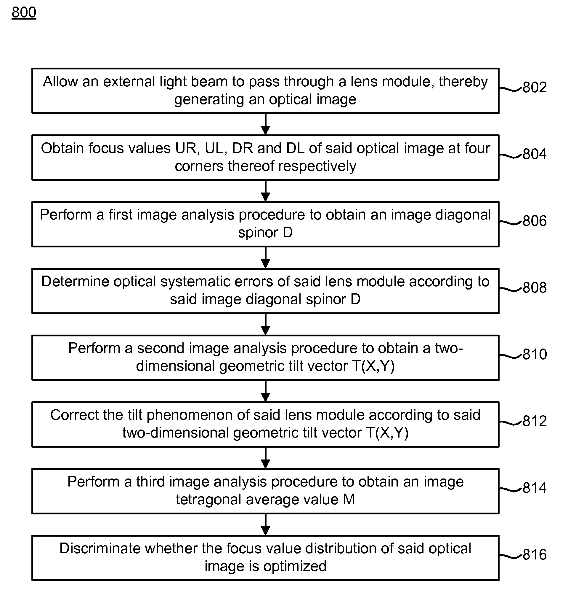
[0011]In accordance with a first aspect of the present invention, there is provided a focus adjustable method comprising steps of allowing an external light beam to pass through a lens module, thereby generating an optical image; obtaining focus values UR, UL, DR and DL of the optical image at four corners thereof; performing a first image analysis procedure to obtain a two-dimensional geometric tilt vector T(X,Y) according to the formula: T(X,Y)=(X2+Y2)1 / 2, ∠ arctan(Y / X), where X=[(DR+UR)−(UL+DL)] / b, Y=[(UR+UL)−(DR+DL)] / a, and a and b are correction factors for correcting the aspect ratio; and correcting the tilt phenomenon of the lens module according to the two-dimensional geometric tilt vector T(X,Y) so as to achieve a more uniform focusing effect of the optical image.
[0017]In an embodiment, the focus adjustable method further comprises steps of performing a second image analysis procedure to obtain a two-dimensional geometric tilt vector T(X,Y) according to the formula: T(X,Y)=(X2+Y2)1 / 2, ∠arctan(Y / X), where X=[(DR+UR)−(UL+DL)] / b, Y=[(UR+UL)−(DR+DL)] / a, and a and b are correction factors for correcting the aspect ratio; and correcting the tilt phenomenon of the lens module according to the two-dimensional geometric tilt vector T(X,Y) so as to achieve a more uniform focusing effect of the optical image.
[0020]In an embodiment, the focus adjustable method further comprises steps of performing a second image analysis procedure to obtain a two-dimensional geometric tilt vector T(X,Y) according to the formula: T(X,Y)=(X2+Y2)1 / 2, ∠ arctan(Y / X), where X=[(DR+UR)−(UL+DL)] / b, Y=[(UR+UL)−(DR+DL)] / a, and a and b are correction factors for correcting the aspect ratio; and correcting the tilt phenomenon of the lens module according to the two-dimensional geometric tilt vector T(X,Y) so as to achieve a more uniform focusing effect of the optical image.

Problems solved by technology

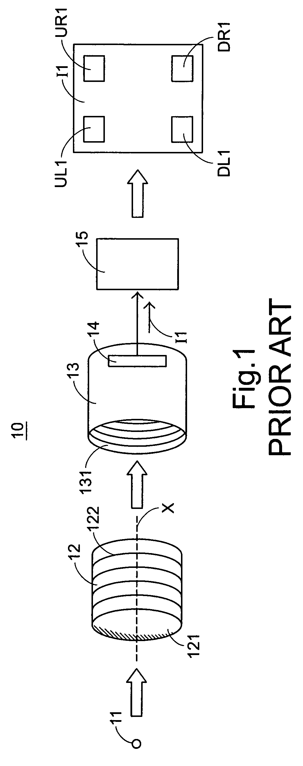
Unfortunately, during the focus adjusting process, the lens module 12 and / or the image sensor 14 is readily tilted.
As known, this unsuccessful focusing adjustment may be caused by a fact that the lens holding jag 13 can move only along the X-axis direction.
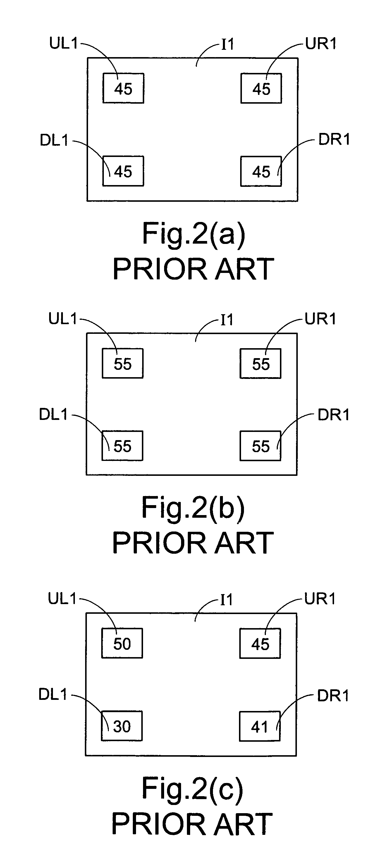
Moreover, since the tilt amount and the tilt angle are not clearly realized according to the prior art, the problem of generating uneven focus values is hard to be overcome.
The conventional focus adjustable method fails to discriminate whether the inherent imaging tolerance influences the focusing performance.
Furthermore, the conventional focus adjustable method fails to evaluate the overall focusing performance after the lens module 12 is adjusted.

Method used


Image

  • Focus adjustable method of optical image
  • Focus adjustable method of optical image
  • Focus adjustable method of optical image

Examples


Embodiment Construction

[0034]The present invention will now be described more specifically with reference to the following embodiments. It is to be noted that the following descriptions of preferred embodiments of this invention are presented herein for purpose of illustration and description only. It is not intended to be exhaustive or to be limited to the precise form disclosed.

[0035]Referring to FIG. 3, a focus adjustable system for generating an optical image having four corners' focus values according to the present invention is illustrated. In the focus adjustable system 20 of FIG. 3, an external light beam 21 passes through a lens surface 221 of a lens module 22, and is then projected onto an image sensor 24 equipped in a lens holding jag 23. After the light beam is imaged on the image sensor 24, an optical image I2 is outputted to a microprocessor 25. By a so-called full screen algorithm or a modulation transfer function (MTF) algorithm, the focus values UL2, UR2, DL2 and DR2 of the optical image ...


PUM


Abstract

A focus adjustable method of an optical image is implemented by a numerical analysis. An external light beam is allowed to pass through a lens module, thereby generating an optical image. The focus values of the optical image at four corners thereof are computed according to specified formulas to obtain a two-dimensional geometric tilt vector T(X,Y), an image diagonal spinor D and an image tetragonal average value M. According to the values T(X,Y), D and M, the tilt amount and the tilt direction of the lens module are adjusted, the optical quality of the lens module is discriminated and the focus value distribution of the lens module is determined.

Description

FIELD OF THE INVENTION[0001]The present invention relates to a focus adjustable method of an optical image, and more particularly to an automatic focus adjustable method of an optical image by performing a numerical analysis on the focus values at four corners of the optical image.BACKGROUND OF THE INVENTION[0002]Currently, an optical lens module is widely used in an electronic product such as a videophone or a mobile phone's camera. In order to adjust, calibrate or detect the focusing operations of the optical lens module, the workers may manually rotate the optical lens module, which is engaged with a lens holding jag having an image sensor therein, to have the lens module rotate up and down along the lens' axis.[0003]Referring to FIG. 1, a conventional focus adjustable system for generating an optical image having four corners' focus values is illustrated. In the focus adjustable system 10 of FIG. 1, an external light beam 11 passes through a lens surface 121 of a lens module 12,...

Claims


Application Information

Patent Timeline
Patent Type & Authority Patents(United States)
IPC IPC(8): G03B3/00G03B13/00
CPCG03B13/36G02B7/36
Inventor CHIN, HOU-CHINGCHANG, CHIH-CHIEN
Owner PRIMAX ELECTRONICS LTD
Why Eureka
Try Eureka