Systems and methods for power generation and hydrogen production with carbon dioxide isolation

a technology of power generation and hydrogen production, which is applied in the direction of machines/engines, mechanical equipment, energy input, etc., can solve the problems of increasing economic and legislative constraints on cosub>2/sub>, removing or recovering cosub>2/sub> from power generation systems, such as the exhaust of gas turbines, and generally not economical,

Inactive Publication Date: 2009-12-22
GENERAL ELECTRIC CO
View PDF14 Cites 95 Cited by
  • Summary
  • Abstract
  • Description
  • Claims
  • Application Information

AI Technical Summary

Problems solved by technology

Currently, there is a trend towards increasing economic and legislative constraints on CO2 emissions to the atmosphere from power plants, for example, Kyoto Protocol, emission taxes, European Emissions Trading Scheme, etc.
Removal or recovery of the carbon dioxide (CO2) from power generation systems, such as from the exhaust of a gas turbine, is generally not economical due to low CO2 content and low (ambient) pressure of the exhaust.
Therefore, unfortunately, the exhaust containing the CO2 is typically released to the atmosphere, and does not get sequestered into oceans, mines, oil wells, or geological saline reservoirs.

Method used


Image

  • Systems and methods for power generation and hydrogen production with carbon dioxide isolation
  • Systems and methods for power generation and hydrogen production with carbon dioxide isolation
  • Systems and methods for power generation and hydrogen production with carbon dioxide isolation

Examples


Embodiment Construction

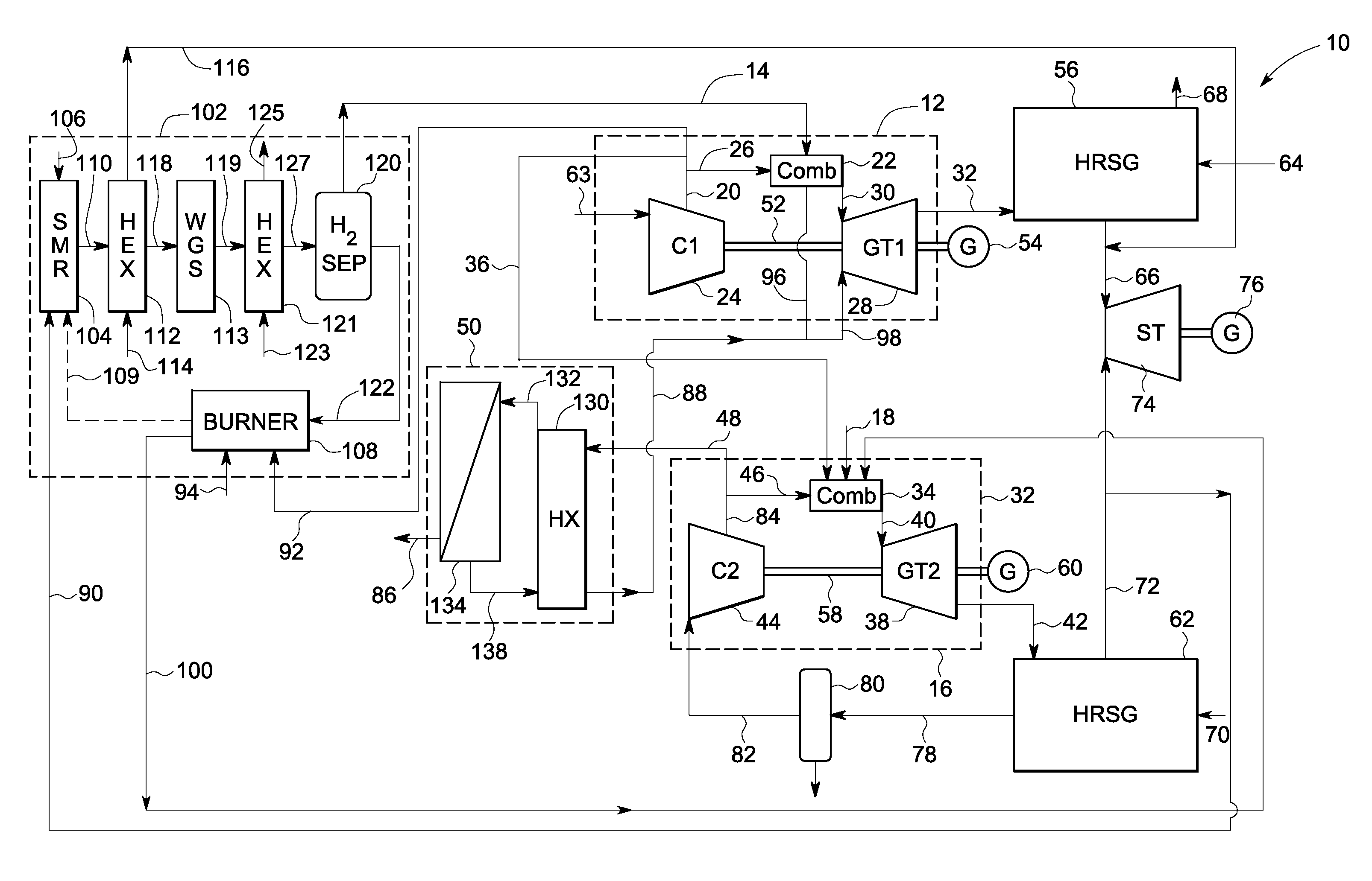
[0012]The present technique provides for two or more exemplary gas turbine systems operating in a power generation system to share a common supply of compressed oxidant. As a result, compression capacity may be freed in one or more of the turbine systems to be employed in the recovery of carbon dioxide (CO2) generated by one or more of the turbine systems. In one example, a compressor in a first turbine system supplies oxidant (via conduits) to a combustion chamber in the first turbine system and also to a combustion chamber in a second turbine system, freeing a compressor in the second turbine system. As discussed below, this freed compression capacity may be employed in the separation and recovery of carbon dioxide (CO2) and other components from the exhaust of one or more of the gas turbines. The recovered CO2 may be sold as product or consumed on-site as feed in other processes, for example. Further, such recovery of CO2 may reduce the amount of CO2 emitted to the environment fr...


PUM


Abstract

A power generation system includes a first gas turbine system. The first turbine system includes a first combustion chamber configured to combust a first fuel stream of primarily hydrogen that is substantially free of carbon-based fuels, a first compressor configured to supply a first portion of compressed oxidant to the first combustion chamber and a first turbine configured to receive a first discharge from the first combustion chamber and generate a first exhaust and electrical energy. The power generation system further includes a second gas turbine system. The second turbine system includes a second combustion chamber configured to combust a second fuel stream to generate a second discharge, wherein the first compressor of the first gas turbine system is configured to supply a second portion of compressed oxidant to the second combustion chamber and a second turbine configured to receive the second discharge from the second combustion chamber to generate a second exhaust and electrical energy. A second compressor is configured to receive the second exhaust comprising carbon dioxide and to discharge a recycle stream to the second combustion chamber and a split stream to a separator system adapted to recover carbon dioxide. The power generation system also includes a hydrogen generation system configured to receive a third fuel and steam to generate the first fuel and a third exhaust gas, wherein the third exhaust gas is recycled into the second combustion chamber.

Description

BACKGROUND OF THE INVENTION[0001]The invention relates generally to power generation and the efficient recovery of carbon dioxide. More particularly, the invention relates to the integration of power generation plants with hydrogen production and carbon dioxide separation and recovery.[0002]Currently, the most cost effective method of producing hydrogen is centralized steam reforming of fuels such as natural gas. Rising energy prices and concern for the environment are prompting increased attention to hydrogen as an energy source. Hydrogen has been proposed as a clean fuel for the future with many applications including for use with vehicles and with stationary power.[0003]Power generation systems that combust fuels containing carbon for example, fossil fuels, produce carbon dioxide (CO2) as a byproduct as carbon is converted to CO2 during the combustion process. Currently, there is a trend towards increasing economic and legislative constraints on CO2 emissions to the atmosphere fr...

Claims


Application Information

Patent Timeline
Patent Type & Authority Patents(United States)
IPC IPC(8): F02C3/28F02C6/08F02C6/18
CPCC01B3/38F01K23/10F02C3/22F02C6/18Y02E20/185C01B2203/0244C01B2203/0255C01B2203/0261C01B2203/04C01B2203/0405C01B2203/0415C01B2203/043C01B2203/046C01B2203/0475C01B2203/06C01B2203/066C01B2203/0811C01B2203/0822C01B2203/0827C01B2203/0894C01B2203/1058C01B2203/1223C01B2203/1229C01B2203/1241C01B2203/1247C01B2203/84C01B2203/86F05D2220/74F05D2220/72C01B2203/0233Y02E20/18Y02P20/10Y02P20/129Y02P30/00
Inventor HOFFMANN, STEPHANIE MARIE-NOELLEBARTLETT, MICHAEL ADAM
Owner GENERAL ELECTRIC CO
Why Eureka
Try Eureka