Device for the control at least of a hydraulically operable switching element of an automatic transmission

a technology of hydraulic operability and automatic transmission, which is applied in the direction of fluid actuated clutches, mechanical equipment, fluid actuated clutches, etc., can solve the problems of spring-operated accumulators, difficult or not at all feasible starting of vehicles from standstill with high gear in automatic transmission, etc., and achieve the effect of avoiding erroneous transmission activation

Active Publication Date: 2009-12-22
ZF FRIEDRICHSHAFEN AG
View PDF10 Cites 9 Cited by
  • Summary
  • Abstract
  • Description
  • Claims
  • Application Information

AI Technical Summary

Benefits of technology

[0019]For this reason, erroneous activations in the transmission are avoided through a constructively simple design of the additional switch piston and of the valve housing of the position valve mechanism corresponding to it in a cost-efficient manner which, for example, with automatic transmission known from experience, is prevented through cost-intensive pressure sensors and valve-way sensors, by way of which a false activation on the part of the transmission device is ascertainable before a gear change and consequential laborious error logging.

Problems solved by technology

Since with a high gear in the output of a vehicle only minor tractive forces are present, a start of a vehicle from standstill with high gear put in the automatic transmission is difficult or not at all feasible.
As soon as such a spring-operated accumulator is emptied or the spring stops, the pressure supply to the clutch also collapses here.
Such spring-operated accumulators are, therefore, only suitable to bridge short-term electronic failures, for example, for a time span of 20 milliseconds, during which a changeover of the valve would otherwise already occur.
However, it is disadvantageous that the duration of time available for the suggested device is possibly inadequate for safe malfunction detection on the transmission side and switching elements are activated in the transmission, which do not correspond with an operating condition needing adjustment of the automatic transmission.

Method used


Image

  • Device for the control at least of a hydraulically operable switching element of an automatic transmission
  • Device for the control at least of a hydraulically operable switching element of an automatic transmission
  • Device for the control at least of a hydraulically operable switching element of an automatic transmission

Examples


Embodiment Construction

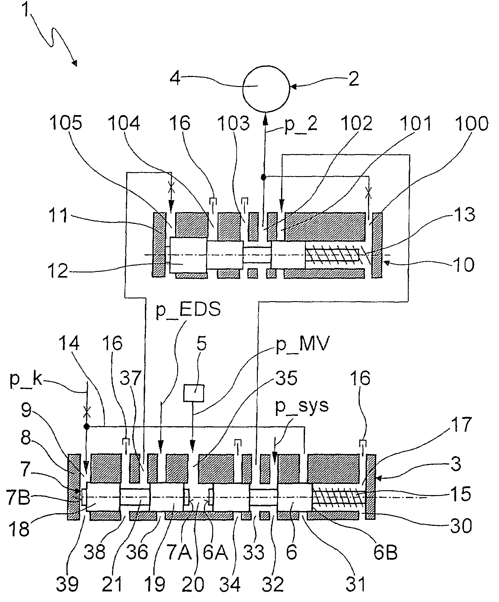
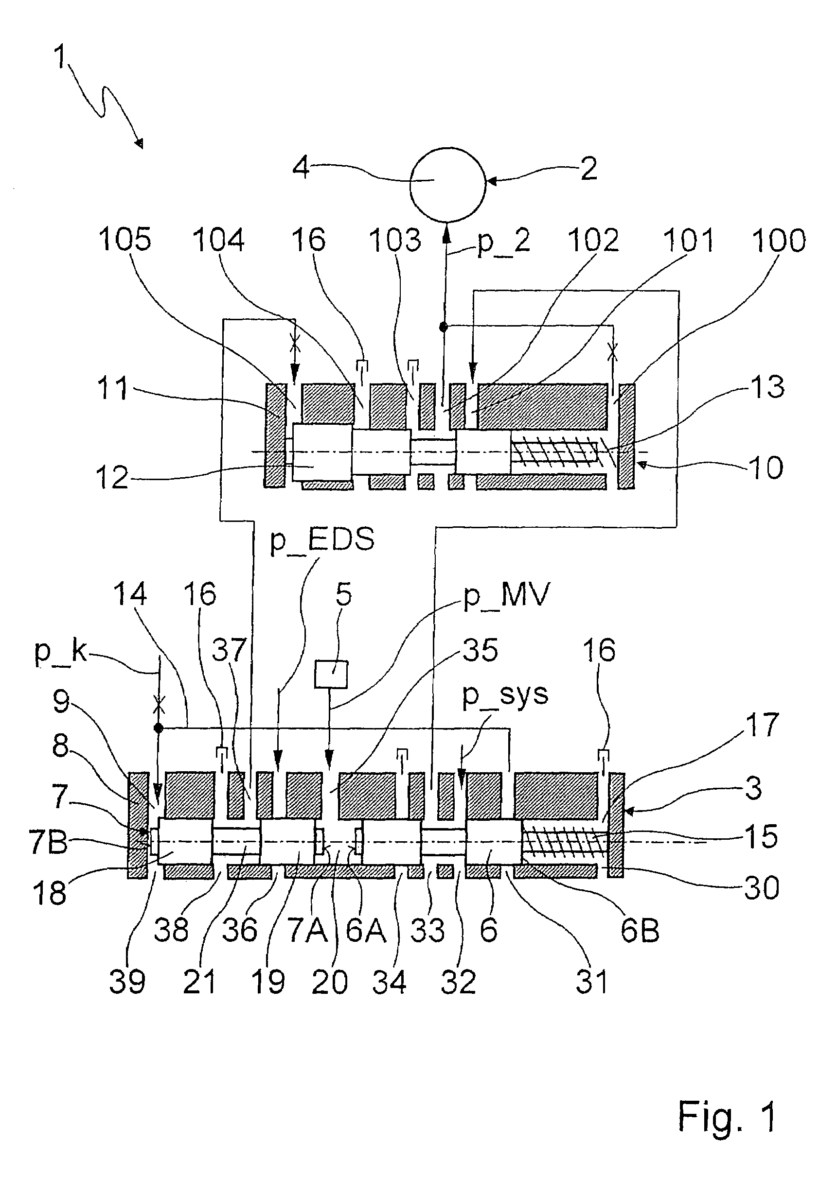
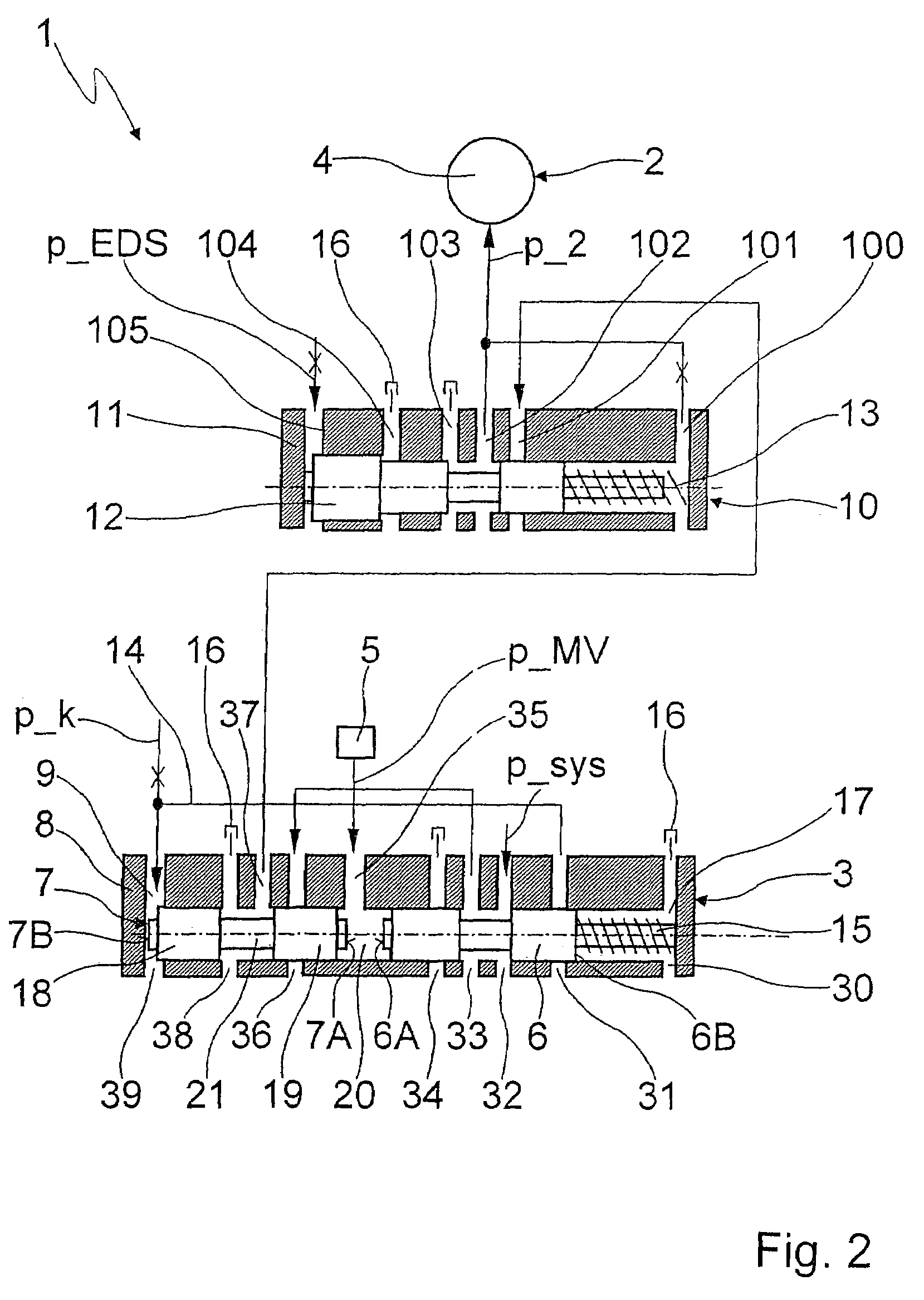
[0024]FIG. 1 shows a device 1 for controlling at least a hydraulically operable switching element 2 of an automatic transmission of a vehicle (not shown), which is activated by a known electrified hydraulic switching device or a gearbox with a position valve mechanism 3 designed as a pressure control valve and a valve mechanism 10 actively connecting with it and implemented as a pressure regulation valve.

[0025]The switching element 2 is a frictional disk clutch, whose frictional disks can be brought more or less strongly into frictional contact with one another via hydraulic piston mechanism in an known manner to adjust transmission capacity. For simplicity only, a clutch area 4 of the piston mechanism, shown in the diagram, is acted upon via the position valve mechanism 3 and the valve mechanism or the pressure regulation mechanism 10 with a pilot pressure p—2 required for the adjustment of transmission capacity.

[0026]The position valve mechanism 3 contains an admittable main switc...


PUM


Abstract

A device for controlling a hydraulically operable switching element (2) of an automatic transmission of a vehicle with a position valve mechanism (3) having a main switch piston (6) which is spring biased into a first switch position and a second switch position with a pilot pressure (P_MV) which is adjustable through an electrically operated actuator (5). An additional switch piston (7) and the main switch piston (6) are axially actuated in a valve housing (8). Depending on the position of the pistons (6, 7), faces (6A, 7A) of the respective pistons are either spaced apart or adjacent. The additional switch piston (7) is adjustable depending on a pilot pressure (p_K) of a switching element which engages a gear for forward drive.

Description

[0001]This application claims priority from German Application Serial No. 10 2005 029 589.4 filed Jun. 25, 2005.FIELD OF THE INVENTION[0002]The invention concerns a device for the control at least of a hydraulically operable switching element of an automatic transmission of a vehicle with a position valve mechanism.BACKGROUND OF THE INVENTION[0003]In the operation of automatic transmissions known from the operation of automobiles, switching elements implemented as clutches or brakes are operated depending on a driver-sided, currently selected operating gear, as for example “forward-drive,’“reverse-drive, “neutral,” or “park” and a current working condition of the vehicle via an hydraulic control. In order to reduce the required design envelope, such automatic transmissions are activated by a so-called electrified hydraulic switching device, by way of which a driver-desired input requirement is transferred via an electrically active connection between an operator control provided for...

Claims


Application Information

Patent Timeline
Patent Type & Authority Patents(United States)
IPC IPC(8): F16D48/06F16D25/12F16H61/18F16H61/12
CPCF16H61/0206F16H61/12Y10T74/19251F16H2061/0253Y10T477/693635F16H2061/1292
Inventor GIERER, GEORGSCHMIDT, THILOHERRMANN, MARKUS
Owner ZF FRIEDRICHSHAFEN AG
Why Eureka
Try Eureka