Projector

a projector and projection technology, applied in the field of projectors, can solve the problems of user might lose a certain projection reference position, dial knob vibration and click sound, etc., and achieve the effect of convenient user understanding, simple configuration and preferable operability

Inactive Publication Date: 2009-12-22
COLUMBIA PEAK VENTURES LLC
View PDF9 Cites 5 Cited by
  • Summary
  • Abstract
  • Description
  • Claims
  • Application Information

AI Technical Summary

Benefits of technology

[0010]An advantage of the invention is to provide a projector with preferable operability.
[0011]In order to gain the advantage, a projector according to an aspect of the invention includes a light source, an optical modulation device that modulates light beam emitted from the light source in accordance with image information to form an optical image, a projection optical device that projects the optical image formed by the optical modulation device in an enlarged manner, a projection position adjusting device that moves the projection optical device in a plane perpendicular to a projection direction to adjust the projection position of the projection optical device, wherein, the projection position adjusting device includes a fixed member fixed to the projector, a moving member capable of moving along the plane perpendicular to the projection direction with respect to the fixed member, a dial knob supported rotatably with respect to the fixed member and operable by a user, a drive mechanism that is engaged with the moving member and the dial knob, and transmits rotation of the dial knob to the moving member to move the moving member, a reference position detecting mechanism that is disposed between the fixed member and the dial knob, and detects a projection reference position of the projection optical device, the reference position detecting mechanism including a guiding section provided to a side face of the dial knob adjacent to the fixed member, along the rotational direction of the dial knob, and shaped like a groove, a sliding section that is provided to the fixed member, and slides in the guiding section in accordance with the rotation of the dial knob, and an engaging section that is provided to the guiding section, and engages with the sliding section in the case in which the projection position of the projection optical device reaches the projection reference position.
[0012]Here, as the projection reference position, for example, the center position of the adjustable range of the projection position, namely, the moving path of the projection optical device in a plane perpendicular to the projection direction can be cited.
[0013]According to this aspect of the invention, the user adjusts the projection position of the projector while rotating the dial knob by hand. Then, in the projection position adjusting device of the projector, the moving member is moved in accordance with the rotation of the dial knob, and the projection optical device supported by the moving member is moved along the moving path in a plane perpendicular to the projection direction. In this case, in the reference position detecting mechanism, sliding section slides along the guiding section in accordance with the rotation of the dial knob.
[0014]When the projection position of the projection optical device eventually reaches the projection reference position, the sliding section engages with the engaging section in the guiding section of the reference position detecting mechanism. And, if the dial knob is continued to be rotated, the engagement between the sliding section and the engaging section is released, and the sliding section slides again in the guiding section in accordance with the rotation of the dial knob. In this case, the engagement and release between the sliding section and the engaging section causes the dial knob a slight vibration and click sound. The user who is rotating the dial knob can feel the vibration by hand.
[0015]Thus, while a user is adjusting the projection position turning the dial knob, the user can recognize the projection position when the vibration of the dial knob or the click sound is felt as the reference position. Therefore, according to the projector of this aspect of the invention, it is possible to notice the user that the projection position reaches the reference position in adjusting the projection position, with relatively simple configuration and in a manner easy-to-understand to the user.

Problems solved by technology

However, in the projector described in JP-A-2004-205686, the user might lose a certain projection reference position in the moving path such as the center point of the moving path while adjusting the projection position of the projector by rotating the dial knob.
In this case, the engagement and release between the sliding section and the engaging section causes the dial knob a slight vibration and click sound.
Thus, the vibration caused on the dial knob by the engagement becomes clear.
However, when the dial knob is rotated in the inverse direction from the direction in which the dial knob has been rotated, the backlash in accordance with the engagement gap between the gears is caused, and an error that the position of engagement between the sliding section and the engaging section is shifted from the projection reference position might be caused in the reference position detecting mechanism.
Since the sliding section is abutted on the rotation stopper, the dial knob becomes impossible to be rotated any further.

Method used


Image

  • Projector
  • Projector
  • Projector

Examples


Embodiment Construction

[0048]An embodiment of the invention will hereinafter be explained with reference to the accompanying drawings.

[0049]1. External Configuration

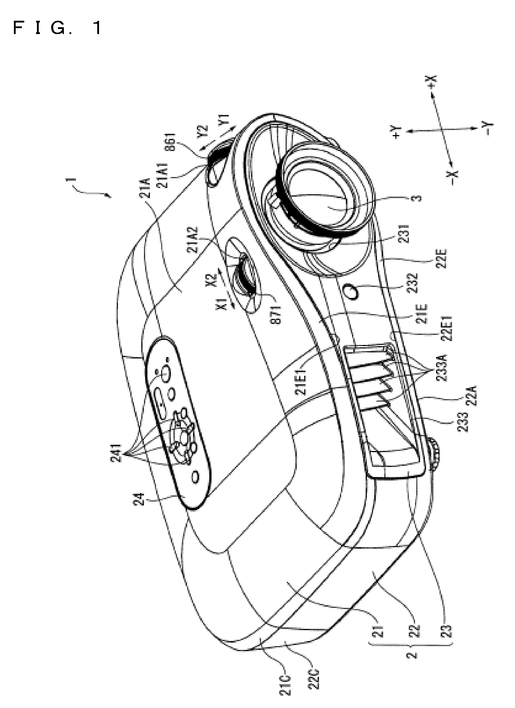
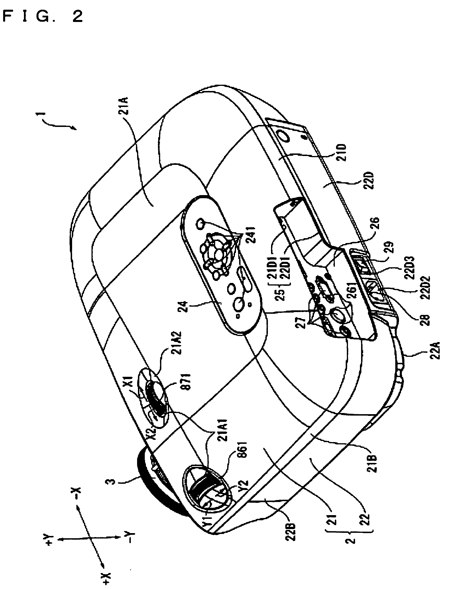
[0050]FIGS. 1 and 2 are the perspective views showing the external appearance of a projector 1. Specifically, FIG. 1 is the perspective view showing the projector 1 viewed from an upper front side thereof. FIG. 2 is the perspective view of the projector 1 viewed from an upper rear side thereof.

[0051]The projector 1 is for forming an optical image by modulating an optical beam emitted from the light source in accordance with image information, and projecting the formed optical image on a screen (not shown) in an enlarged manner. As shown in FIG. 1 or 2, the projector 1 is provided with a substantially cuboid shaped exterior chassis 2, and a projection lens 3 as the projection optical device exposed from the exterior chassis 2.

[0052]The projection lens 3 is configured as a set of lenses composed of a plurality of lenses housed in a cylindrical b...


PUM


Abstract

A projector includes a light source, an optical modulation device to form an optical image, a projection optical device, and a projection position adjusting device to adjust the projection position. The projection position adjusting device includes a fixed member, a moving member a dial knob, a drive mechanism that transmit rotation of the dial knob, and a reference position detecting mechanism. The reference position detecting mechanism includes a spiral rail guiding section having a groove shape provided to a side face of the dial knob adjacent to the fixed member, along the rotational direction of the dial knob, a sliding section that slides in the guiding section with the rotation of the dial knob, and an engaging section provided to the guiding section, and engages with the sliding section upon the projection position of the projection optical device reaching the projection reference position.

Description

BACKGROUND[0001]1. Technical Field[0002]The present invention relates to a projector.[0003]2. Related Art[0004]In the past, a projector provided with a light source lamp, a liquid crystal panel for modulating light beam emitted from the light source lamp in accordance with image information, and a projection lens in an enlarged manner for projecting the modulated light beam to the outside has been known.[0005]When using a projector, there are some cases in which the projected image needs to be displayed shifted in a vertical or a horizontal direction on the screen while keeping the setting posture of the projector. In accordance with such a need, a projector equipped with a projection position adjusting device has been provided (for example, refer to JP-A-2004-205686). The projection position adjusting device is a device capable of moving the projection lens along a plane perpendicular to the projection direction. The projector equipped with such a projection position adjusting devi...

Claims


Application Information

Patent Timeline
Patent Type & Authority Patents(United States)
IPC IPC(8): G03B21/14G02B7/02G03B21/22G03B3/00
CPCG03B21/14G03B5/02G03B21/142
Inventor NAKAMURA, KUNIHISA
Owner COLUMBIA PEAK VENTURES LLC
Why Eureka
Try Eureka