Capacity-variable type swash plate compressor

a compressor and variable type technology, applied in the direction of machines/engines, mechanical equipment, positive displacement liquid engines, etc., can solve the problems of affecting the durability, generating abnormal sounds, and impairment of capacity controllability, so as to reduce manufacturing costs and facilitate the operation of link mechanisms

Inactive Publication Date: 2009-04-30
TOYOTA IND CORP
View PDF8 Cites 20 Cited by
  • Summary
  • Abstract
  • Description
  • Claims
  • Application Information

AI Technical Summary

Benefits of technology

[0010]In view of such circumstances, it is an object of the present invention to provide a capacity-variable type swash plate compressor which is capable of realizing the preferable operability of a link mechanism and reduction of the manufacturing cost.
[0015]According to the compressor in the present invention, the first and second intermediate arms are joined while clamping the lug member and the swash plate arm so as to allow a rocking movement by the lug-side pin and the swash-plate-side pin. Then, the inner surface of the first intermediate arm is guided by the outer surface of the lug member and the one side surface of the swash plate arm, and the inner surface of the second intermediate arm is guided by the outer surface of the lug member and the other side surface of the swash plate arm. In this manner, with this compressor, generation of abnormal sounds is avoided, and the link mechanism is smoothly operated. With this compressor, the accuracy of machining of the parallel surfaces of the lug member, the swash plate arm, and the first and second intermediate arms may be lowered, and necessity to select the components strictly for assembly is eliminated, so that reduction of the manufacturing cost is realized.
[0016]According to the compressor in the present invention, since the first and second intermediate arm are integrally joined via the lug-side pin and the swash-plate-side pin, the first and second intermediate arms do not move independently, and hence the first and second intermediate arms and thus the swash plate are not displaced from the normal positions and are hardly distorted. According to the compressor in the present invention, since the necessity of forming the lug arm on the lug member is eliminated, manufacture of the lug member and thus of the entire compressor is simplified.
[0017]Therefore, the capacity-variable type swash plate compressor according to the present invention is able to realize the preferable operability of the link mechanism and the reduction of manufacturing cost. The preferable operability of the link mechanism leads to the superior capacity controllability and the superior durability of the compressor.

Problems solved by technology

Otherwise, generation of abnormal sounds, impairment of capacity controllability due to failure of smooth movement of the link mechanism, or impairment of durability due to abrasion of the link mechanism may be resulted.
Therefore, in this compressor, labors to manufacture components of the link mechanism with high degree of accuracy and to select the components before assembly are required, which causes appreciation of manufacturing cost.
In this case as well, the link mechanism is subject to wear and hence the durability of the compressor is periclitated.
However, this means is still insufficient to restrain the distortion.

Method used


Image

  • Capacity-variable type swash plate compressor
  • Capacity-variable type swash plate compressor
  • Capacity-variable type swash plate compressor

Examples


embodiment 1

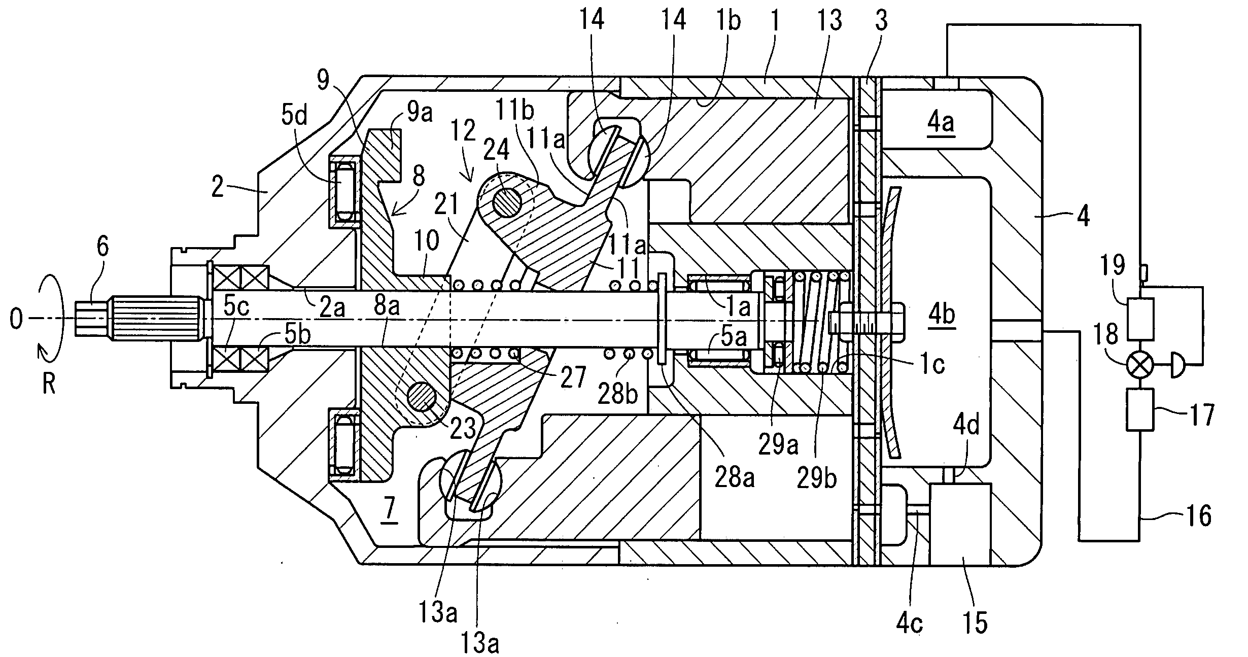
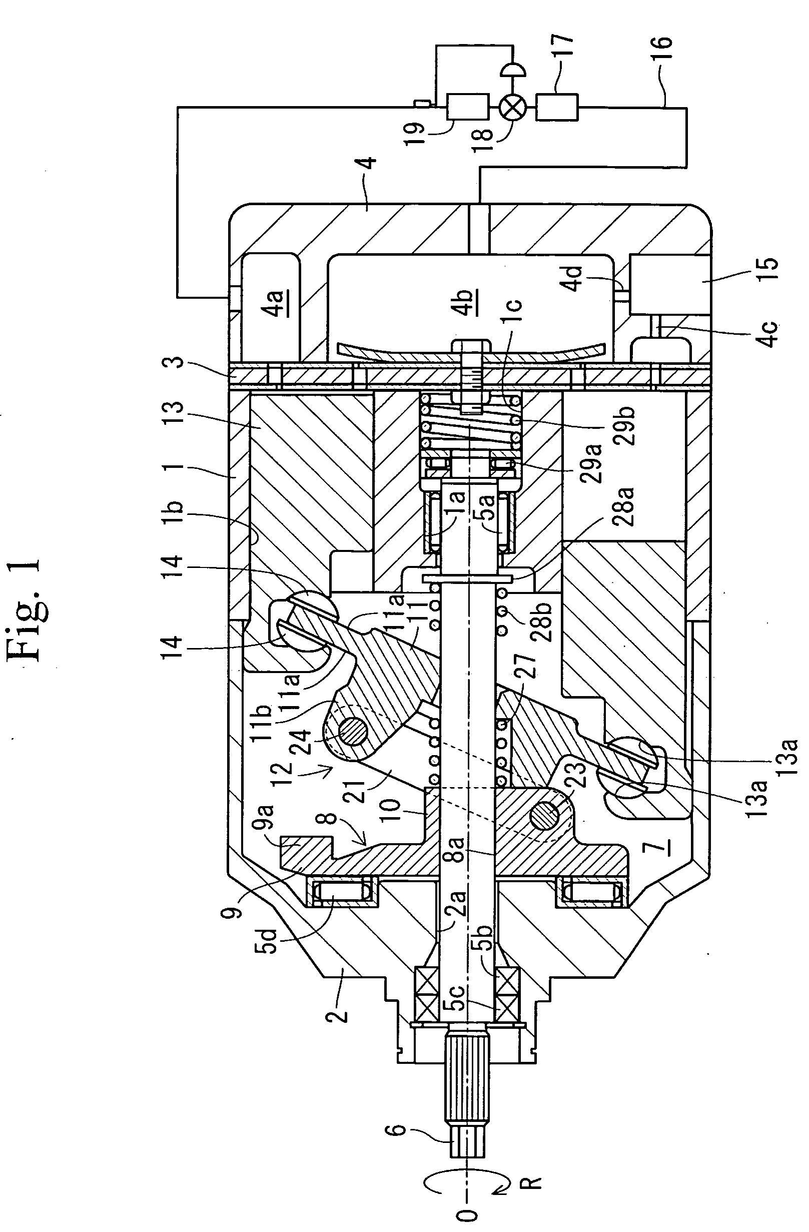
[0058]According to a capacity-variable type swash plate compressor in Embodiment 1, as shown in FIG. 1, a housing includes a cylinder block 1, the front housing 2, and a rear housing 4, a front housing 2 is joined to the front end of the cylinder block 1, and the rear housing 4 is joined to the rear end of the cylinder block 1 via a valve unit 3. The cylinder block 1 and the front housing 2 are formed with shaft holes 1a and 2a extending in the axial direction so as to penetrate therethrough, and a drive shaft 6 is rotatably supported in the shaft holes 1a and 2a via the radial bearings 5a and 5b and a shaft seal device 5c. The left side in FIG. 1 corresponds to the front side, and the right side thereof corresponds to the rear side.

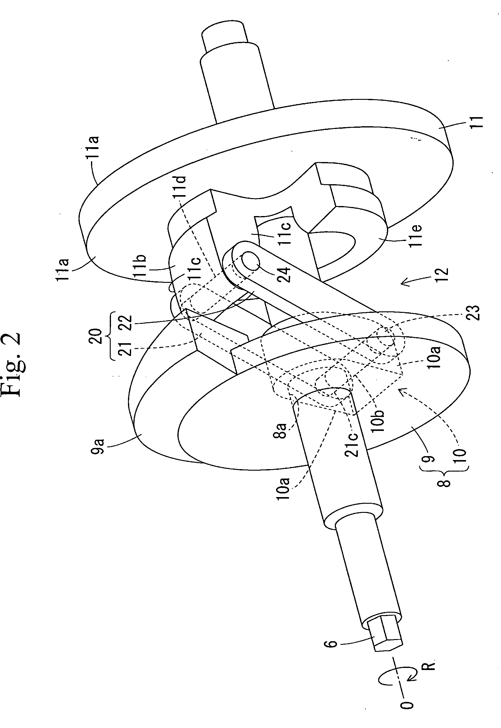
[0059]The front housing 2 and the cylinder block 1 define a crank chamber 7. A lug plate 8 is fixed to the drive shaft 6 in the crank chamber 7. As shown in FIGS. 2 to 4 as well, the lug plate 8 is formed with a press-fitting hole 8a, and the drive shaft...

embodiment 2

[0084]The compressor in Embodiment 2 employs a link mechanism 30 as shown in FIG. 5 and FIG. 6. In the link mechanism 30, an outer spline 31a is formed on a drive shaft 31, and an inner spline 32a is formed on a thrust plate 32, and the outer spline 31a and the inner spline 32a are fitted to each other. In this manner, the thrust plate 32 is clearance-fitted to the drive shaft 31.

[0085]The thrust plate 32 is formed of vibration-control metal alloy. The lug member 33 is formed separately from the thrust plate 32, and comes into abutment with the thrust plate 32. A lug member 33 is formed with a press-fitting hole 33a, and the drive shaft 31 is press-fitted into the press-fitting hole 33a. Other configurations are the same as in Embodiment 1.

[0086]In this compressor, the thrust plate 32 and the lug member 33 are formed separately, and the thrust plate 32 comes into abutment with the lug member 33. Therefore, the thrust plate 32 does not have a function to rotate the swash plate 11 syn...

embodiment 3

[0089]The compressor in Embodiment 3 employs a link mechanism 40 shown in FIG. 7. In the link mechanism 40, part of a drive shaft 41 is used as a lug member 41a. Other configurations are the same as in Embodiment 2.

[0090]In this compressor, control of the press-fitting margin required for press-fitting the lug member 41a into the drive shaft 41 is eliminated. In this compressor, a labor to machine the seat of the thrust plate 32 after having assembled the sub-assembly including the drive shaft 41 (lug member 41a), the thrust plate 32, the link mechanism 40, and the swash plate is eliminated. Other effects and advantages are the same as in Embodiment 2.


PUM


Abstract

A capacity-variable type swash plate compressor in which the preferable operability of a link mechanism and reduction of manufacturing cost are realized is provided. According to the compressor in the present invention, a link mechanism includes one swash plate arm and intermediate arms. The intermediate arms include first and second intermediate arms. The first and second intermediate arms are joined while being rotatably supported by a lug member and the swash plate arm via a lug-side pin which constitutes a lug-side axis and a swash-plate-side pin which constitutes a swash-plate-side axis and clamping the lug member and the swash plate arm via the lug-side pin and the swash-plate-side pin so as to allow a sliding movement.

Description

[0001]This application claims the benefit of priority to Japanese Patent Application No. 2007-259413, filed on Oct. 3, 2007, and Japanese Patent Application No. 2008-107735, filed on Apr. 17, 2008, these contents of which are hereby incorporated herein by reference.BACKGROUND OF THE INVENTION[0002]The present invention relates to a capacity-variable type swash plate compressor.[0003]In the related art, a capacity-variable type swash plate compressor disclosed in JP-A-10-176658 is known. This compressor includes a housing which is composed of a cylinder block, a front housing, and a rear housing, and the cylinder block includes a plurality of cylinder bores penetrated therethrough. The rear housing includes a suction chamber and a discharge chamber which communicates with the respective cylinder bores via a valve unit. A crank chamber is defined by the front housing and the cylinder block, and a drive shaft is rotatably supported by the front housing and the cylinder block. In the cr...

Claims


Application Information

Patent Timeline
Patent Type & Authority Applications(United States)
IPC IPC(8): F01B3/02
CPCF04B27/18F04B27/1072
Inventor OTA, MASAKIKAWAGUCHI, MASAHIROKUBO, HIROSHIMATSUBARA, RYOKIMURA, NAOFUMIYAMASHITA, HIDEHARU
Owner TOYOTA IND CORP
Why Eureka
Try Eureka