Operation microscope

a technology of operation microscope and microscope, which is applied in the field of operation microscope, can solve the problems of poor visibility, hindering the speed and accuracy of operation, and not obtaining good fusion image, and achieve the effect of satisfying operability

Active Publication Date: 2006-07-04
KK TOPCON
View PDF15 Cites 13 Cited by
  • Summary
  • Abstract
  • Description
  • Claims
  • Application Information

AI Technical Summary

Benefits of technology

[0037]According to the present invention, the deflection member is removed to an illumination optical system side, that is, in an opposite direction to a location of an operator and it is unnecessary to provide a convex portion or the like as a space for the retreat on an operator's side. Accordingly, satisfactory operability can be kept.

Problems solved by technology

Therefore, when binocular vision is conducted, there is a problem in which good fusion of the image is not obtained.
Therefore, there is a problem in which the visibility is inferior.
Therefore, this becomes a factor that hinders the speed and the accuracy of the operation.
However, the red reflexes cannot be obtained in the entire observation image at one time.
Therefore, the position of the reflection mirror needs to be shifted every time when a region in which the generation of the red reflex is desired is changed during operation, resulting that the operation microscope is not suitable in operability.
On the other hand, when the operation microscope that can be used for the retina and vitreous body operation as described in Japanese patent laid open No. 2002-350735 is used for a patient with a small pupil such as a glaucoma patient, because the observation light is blocked by the pupil, there is a case where observation cannot be sufficiently conducted.
Accordingly, there is the case where the amount of light in the periphery of the observation image becomes insufficient.
In some cases, observation becomes impossible.
Also, although there is no problem in the stereoscopic microscope for examination, in the operation microscope, there is a fear that a trouble is caused on an operation because a distance from the eye to be operated to an eyepiece (operating distance) becomes longer.

Method used


Image

  • Operation microscope
  • Operation microscope
  • Operation microscope

Examples


embodiment 1

[0051](Embodiment 1)

[0052](Entire and Individual Part structures of Operation Microscope)

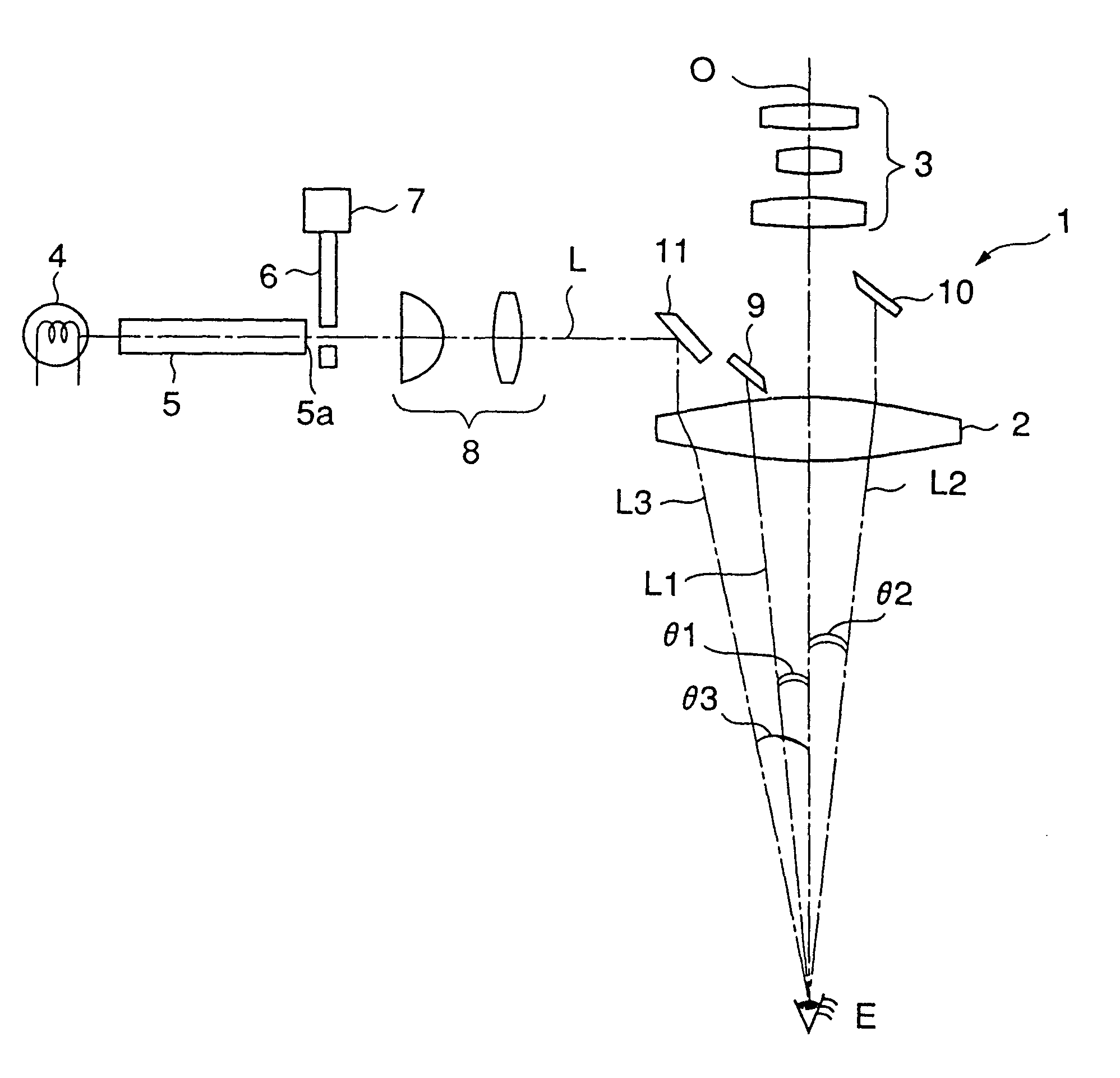
[0053]FIG. 1 shows a schematic structure of an operation microscope 1 according to an embodiment of the present invention. The operation microscope 1 can perform observation with binocular vision and is constructed to include: an objective lens 2 opposed to an eye E of a patient (hereinafter referred to as an eye to be operated) who is undergoing a cataract operation, for example; an eyepiece section (not shown) which is disposed on the extension of the optical axis of the objective lens 2 and provided with left and right eyepieces with which an operator observes the eye to be operated; an observation optical system 3 for guiding an observation light flux to the eyepiece section, which is disposed along the optical axis of the objective lens 2 and composed of a lens group including a variable lens; a light guide 5 for guiding illumination light from a light source 4, which is composed of an opti...

embodiment 2

[0079][Embodiment 2]

[0080]Subsequently, Embodiment 2 of the present invention will be described with reference to the drawing. Embodiment 2 of the present invention is obtained by modifying a part of Embodiment 1 which is described above in detail. FIG. 8 shows a structure of a deflection mirror as a modified part. Note that the same reference symbols as in the description of the operation microscope 1 of Embodiment 1 are used for parts that are not modified.

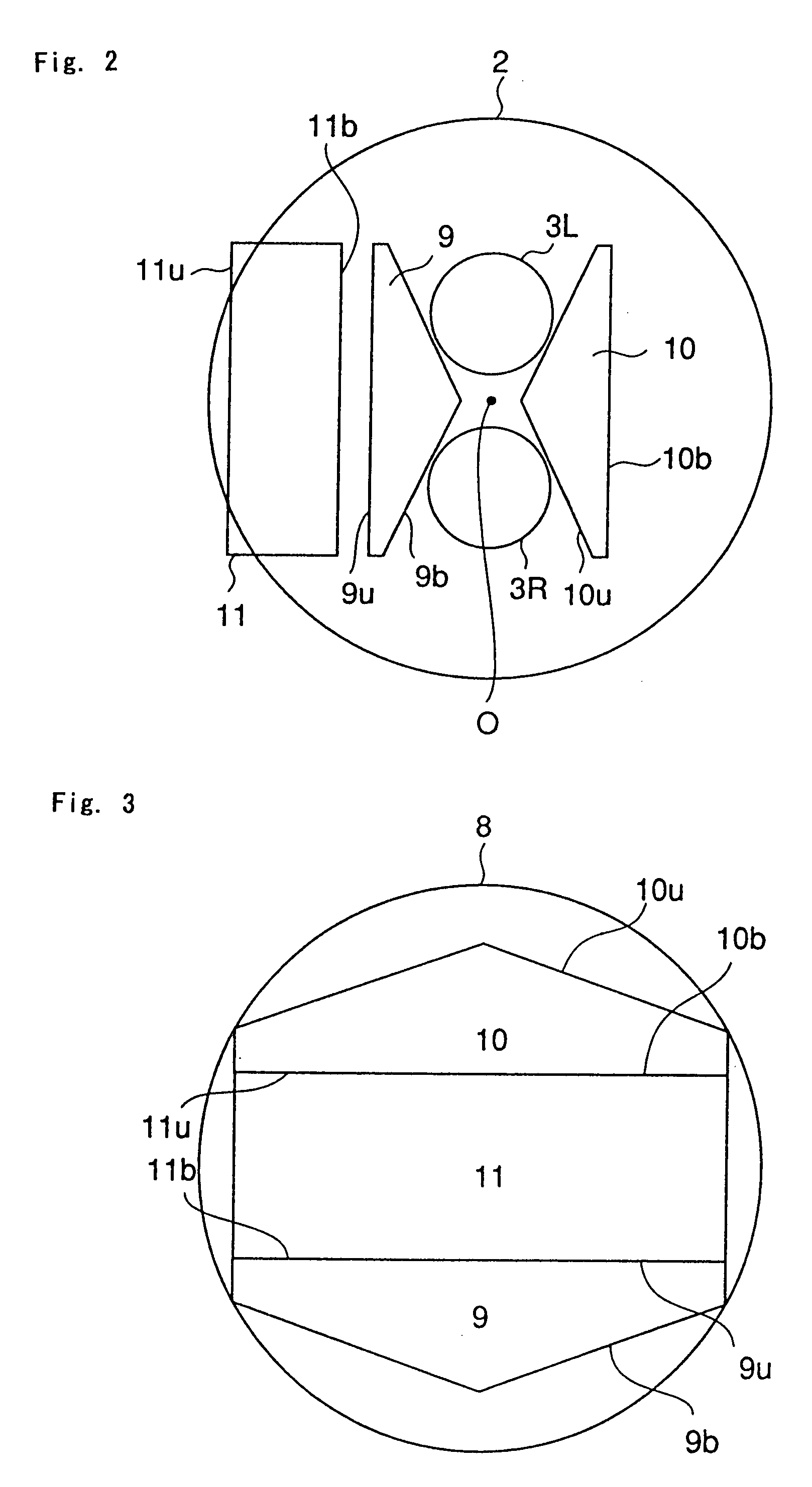
[0081]As shown in FIG. 8, an operation microscope 21 according to Embodiment 2 is obtained by integrally forming the deflection mirrors 9 and 11 described in Embodiment 1. When such integral formation is made, the number of deflection mirrors can be reduced, so that space saving and a reduction in manufacturing cost can be achieved.

[0082]The operation microscope 21 includes a deflection mirror 22 disposed between the illumination optical system 8 and the observation optical axis O and a deflection mirror 23 disposed in an opposi...

embodiment 3

[0089][Embodiment 3]

[0090]In Embodiment 3 of the present invention, a function is added to the above-mentioned operation microscope, thus structuring an operation microscope preferably usable in not only anterior eye segment operation such as cataract operation in which the red reflex is effectively used but also in retina and vitreous body operation for treating further inner organs such as a retina and a vitreous body. FIGS. 9(A) and 9(B) show a schematic structure of an example of such an operation microscope. Here, FIG. 9(A) is a side view of the operation microscope and FIG. 9(B) is a front view thereof. An operator who conducts an operation is located in the right side in FIG. 9(A). FIG. 9(B) is a view when the operation microscope is viewed from the operator's side. In addition, reference symbols provided in Embodiment 1 are correspondingly applied to portions in Embodiment 3, which have the same structure as the operation microscope of Embodiment 1.

[0091]An operation microsc...


PUM


Abstract

Provided is an operation microscope capable of obtaining bright and wide range red reflex on an observation image. Further, an operation microscope suitable for an observation of a retina and a vitreous body is provided. A pair of deflection members composed of two deflection mirrors are provided as a deflection means for deflecting illumination light guided from a light source to the vicinity of an optical axis of an observation optical system and guiding it to an eye to be operated through an objective lens. The deflection mirrors are disposed to sandwich the optical axis therebetween and simultaneously guide the illumination lights to the eye to be operated at substantially the same oblique angles with respect to the optical axis from the respective opposite sides. In addition, a stereo variator is made insertable onto the observation optical axis, so that relative positions of optical axes of right and left observation fluxes can be changed.

Description

BACKGROUND OF THE INVENTION[0001]1. Field of the Invention[0002]The present invention relates to an operation microscope, more particularly to an ophthalmologic operation microscope.[0003]2. Description of the Related Art[0004]Up to now, various ophthalmologic operations have been conducted. In particular, cataract operation is an example of ophthalmologic operations that have been conducted a large number of times. With respect to cataract operation conducted now, a method called a suction technique is common. The suction technique is a method of cutting the front of the capsule of a crystalline lens along the contour thereof, inserting a suction device from the cut edge, sucking the content of the whitish crystalline lens, and implanting an intraocular lens (IOL) therein in place of the sucked content.[0005]When the suction technique is conducted, an operation microscope is used for obtaining an enlarged observation image of an eye to be operated. At this time, in order to improve...

Claims


Application Information

Patent Timeline
Patent Type & Authority Patents(United States)
IPC IPC(8): G02B21/06A61B3/13G02B21/22A61B19/00G02B21/00G02B21/08
CPCA61B3/132G02B21/082G02B21/0012
Inventor OKAMURA, KAZUYUKIKITAJIMA, NOBUAKI
Owner KK TOPCON
Why Eureka
Try Eureka