
Bench-top power tool

Inactive Publication Date: 2006-12-28
POSITEC POWER TOOLS (SUZHOU) CO LTD
View PDF16 Cites 13 Cited by
  • Summary
  • Abstract
  • Description
  • Claims
  • Application Information

AI Technical Summary

Benefits of technology

[0004] One objective of the present invention is to provide a bench-top power tool having at least one movement-adjusting motor with an open control mechanism featuring preferred operability, and cost-effectiveness.
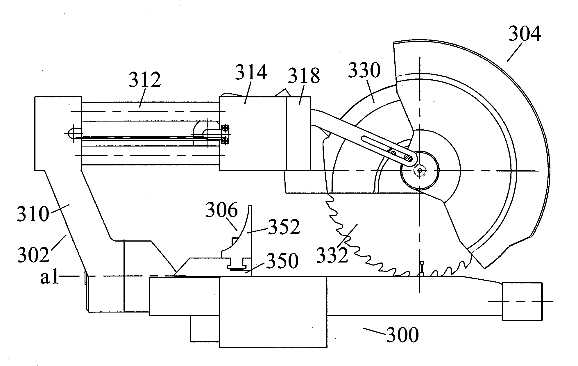
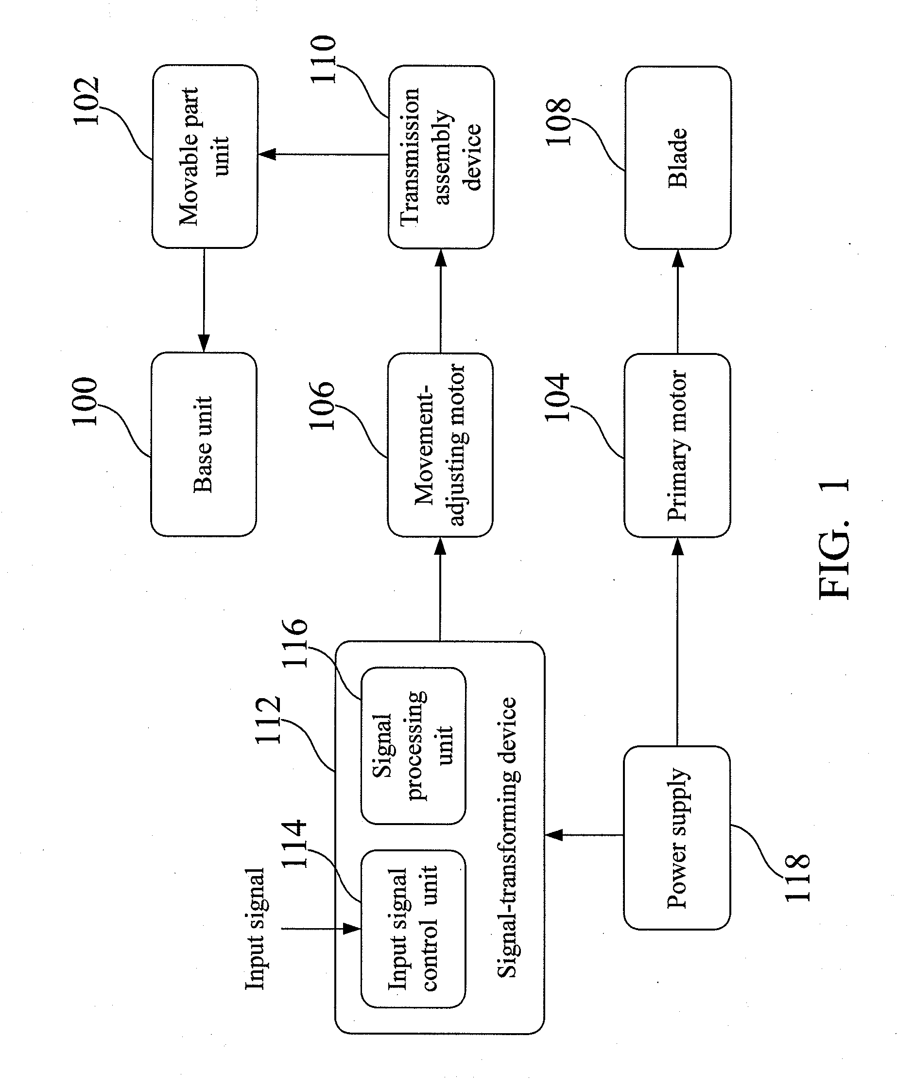
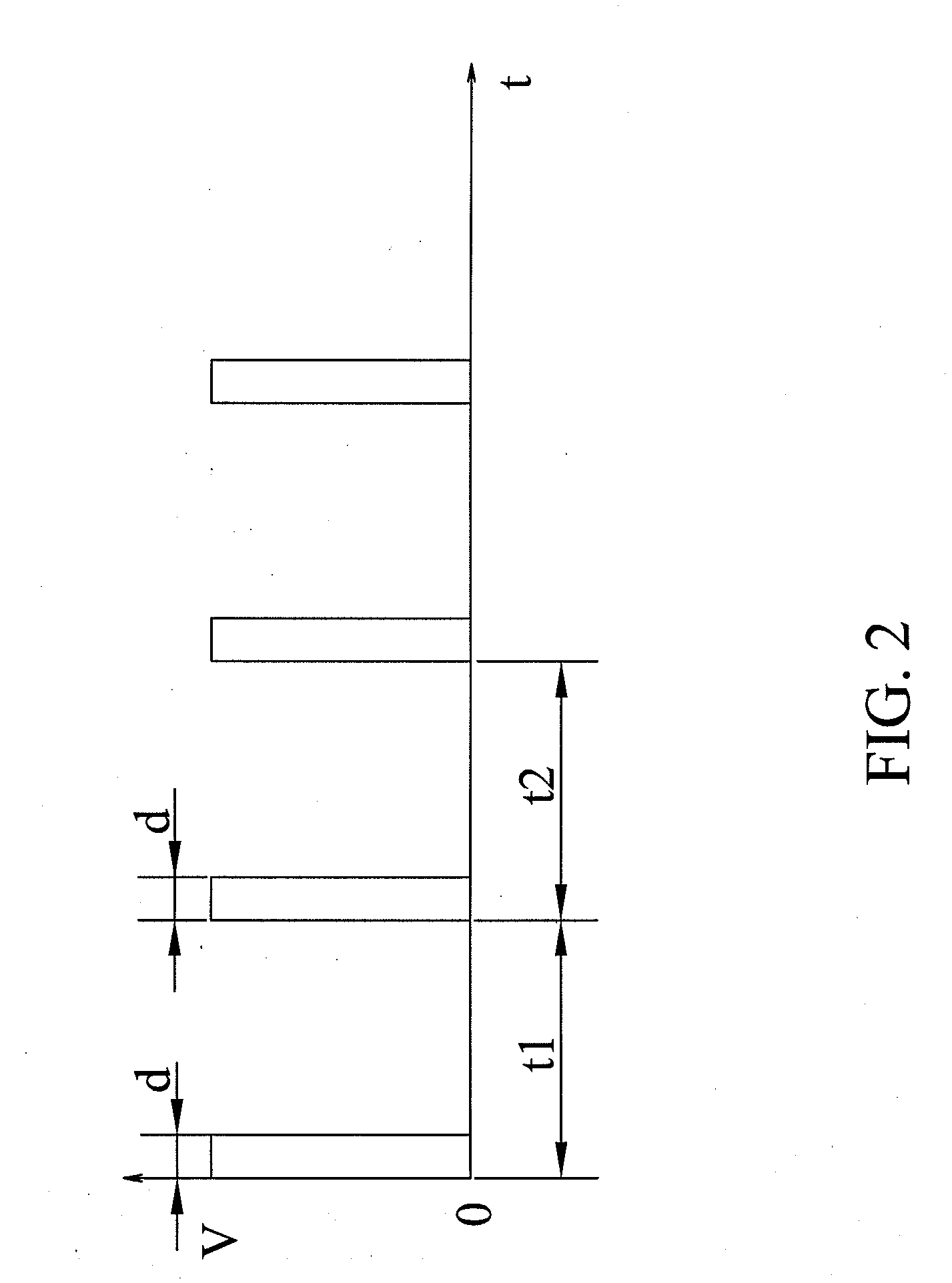
[0007] Preferably, the movement-adjusting motor is connected to the movable part unit via a transmission assembly device. The bench-top power tool further comprises a signal-transforming device for receiving an input signal wherein the signal-transforming device transforms the input signal into a driving signal to drive the movement-adjusting motor. More importantly, the signal-transforming device transforms the input signal into either a continuous or discrete signal and outputs either the continuous or discrete signal into the movement-adjusting motor. Preferably, the movement-adjusting motor is a permanent magnet direct-current (DC) driving motor, a serial motor, a single-phase induction motor, and any combination thereof. That is, the movement-adjusting motor is controlled by an open loop mechanism to reduce cost of the power tool. It should be noted that the bench-top power tool can be a miter saw machine and a bench-top saw machine.
[0011] In comparison with the prior art, the advantages of the present invention generally include: (a) low manufacturing cost; (b) easy to operate; (c) convenient to adjust; and (d) time-saving.

Problems solved by technology

Because a pure mechanical position adjusting device is employed, the adjusting procedure is complicated and time-consuming, therefore the position release and lock are quite complicated.
Furthermore, such a bench tool is extremely troublesome and inconvenient to manipulate.
However, the manufacturing cost is high so that the bevel table-top cutting machine is not suitable for current application in the art.

Method used


Image

  • Bench-top power tool
  • Bench-top power tool
  • Bench-top power tool

Examples


Embodiment Construction

[0042] According to the present invention, the bench-top power tool with at least one movement-adjusting motor with an open control mechanism featuring preferred operability, and cost-effectiveness. Furthermore, while the fast control switch is turned, a continuous signal is outputted into the movement-adjusting motor to drive rapidly the movement-adjusting motor. While the slow control switch is turned, a discrete signal is outputted into the movement-adjusting motor to drive slowly the movement-adjusting motor.

[0043]FIG. 1 is a block diagram of a bench-top power tool according to one embodiment of the present invention. The bench-top power tool comprises a base unit 100, a movable part unit 102, a primary motor 104 and a movement-adjusting motor 106. The movable part unit 102 connected to the base unit 100 is capable of moving in relation to the base unit 100. The primary motor 104 connected to the base unit 102 is used to rotate a blade 108 for cutting a workpiece. The movement-...


PUM


Abstract

A bench-top power tool having at least one movement-adjusting motor for driving movable part unit is described. The bench-top power tool comprises a base unit, a movable part unit, a primary motor and a movement-adjusting motor. The movable part unit connected to the base unit is capable of moving in relation to the base unit. The primary motor connected to the base unit is used to rotate a blade for cutting a workpiece. The movement-adjusting motor connected to the base unit and controlled with an open control mechanism drives the movable part unit to generate a relative motion in relation to the base unit.

Description

FIELD OF THE INVENTION [0001] The present invention relates to a power tool, and more particularly to a bench-top power tool having at least one movement-adjusting motor for driving movable part unit wherein the bench-top power tool is applicable to a miter saw machine and a bench-top saw machine. BACKGROUND OF THE INVENTION [0002] Currently, the position adjustment between working parts applied to the bench tool, such as a bevel cutting tool, is widely done by handling a mechanical adjusting mechanism or a position-adjusting device. Generally speaking, both the position-adjusting device and a locking device are concurrently moved to adjust and lock on the desired position. U.S. Pat. No. 6,532,853 B1 issued on Mar. 18, 2003 discloses a table-top cutting machine. A turntable is also provided and is rotatably supported by the base. A bevel arm is located on the turntable and pivotally connected behind the turntable. A forward extending area is located in the turntable and has a contro...

Claims


Application Information

Patent Timeline
IPC IPC(8): B26D7/06B26D5/08
CPCB23D45/044B23D45/048B23D45/068B27B27/10B23D47/08B23D59/001B23D59/002B23D47/025Y10T83/727Y10T83/8768B23D47/126
Inventor WANG, XINCHEN, SHAODONGBORINATO, GIANNIWANG, LIRENZHOU, XUEJUN
Owner POSITEC POWER TOOLS (SUZHOU) CO LTD
Learn More