Bearing plate for use in an anchor assembly and related method

a technology for bearing plates and anchor assemblies, applied in mining structures, foundation engineering, construction, etc., can solve problems such as insufficient stability of soil properties at construction sites, cracks in current built structures, and other damage, so as to reduce friction, increase the strength of bearing plates, and reduce the amount of experience of friction

Active Publication Date: 2009-12-22
INDEPENDENCE MATERIALS GRP LLC
View PDF16 Cites 22 Cited by
  • Summary
  • Abstract
  • Description
  • Claims
  • Application Information

AI Technical Summary

Benefits of technology

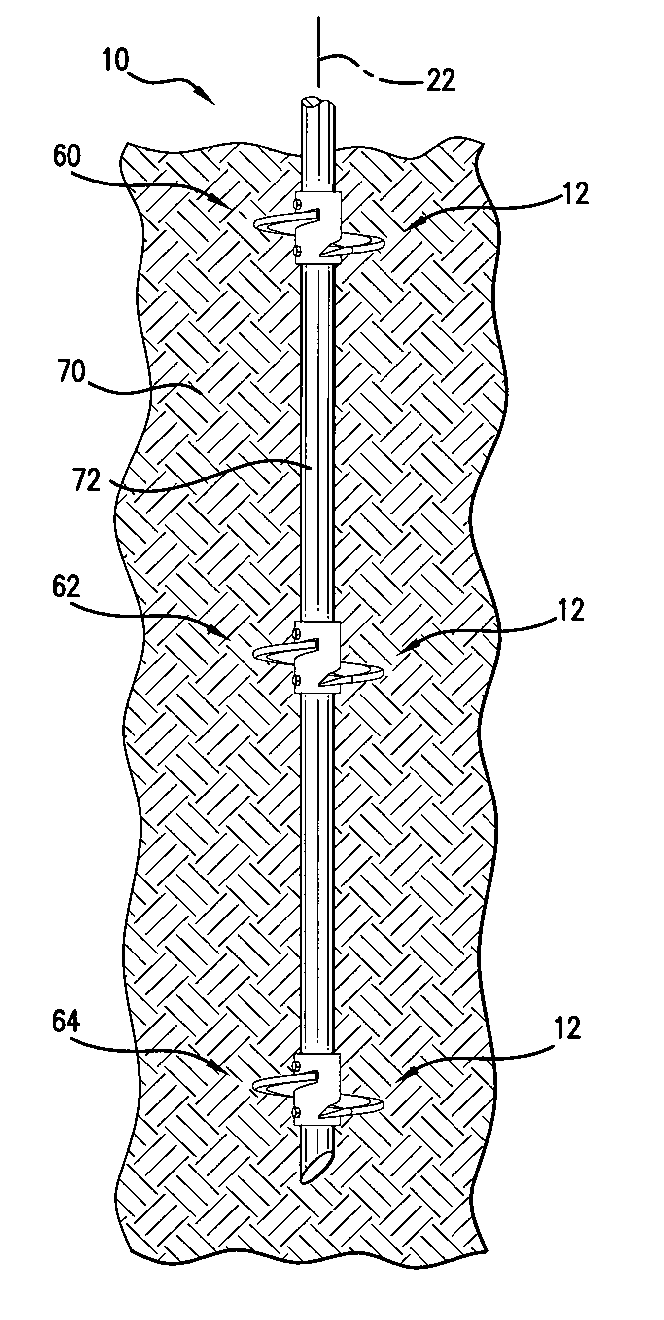
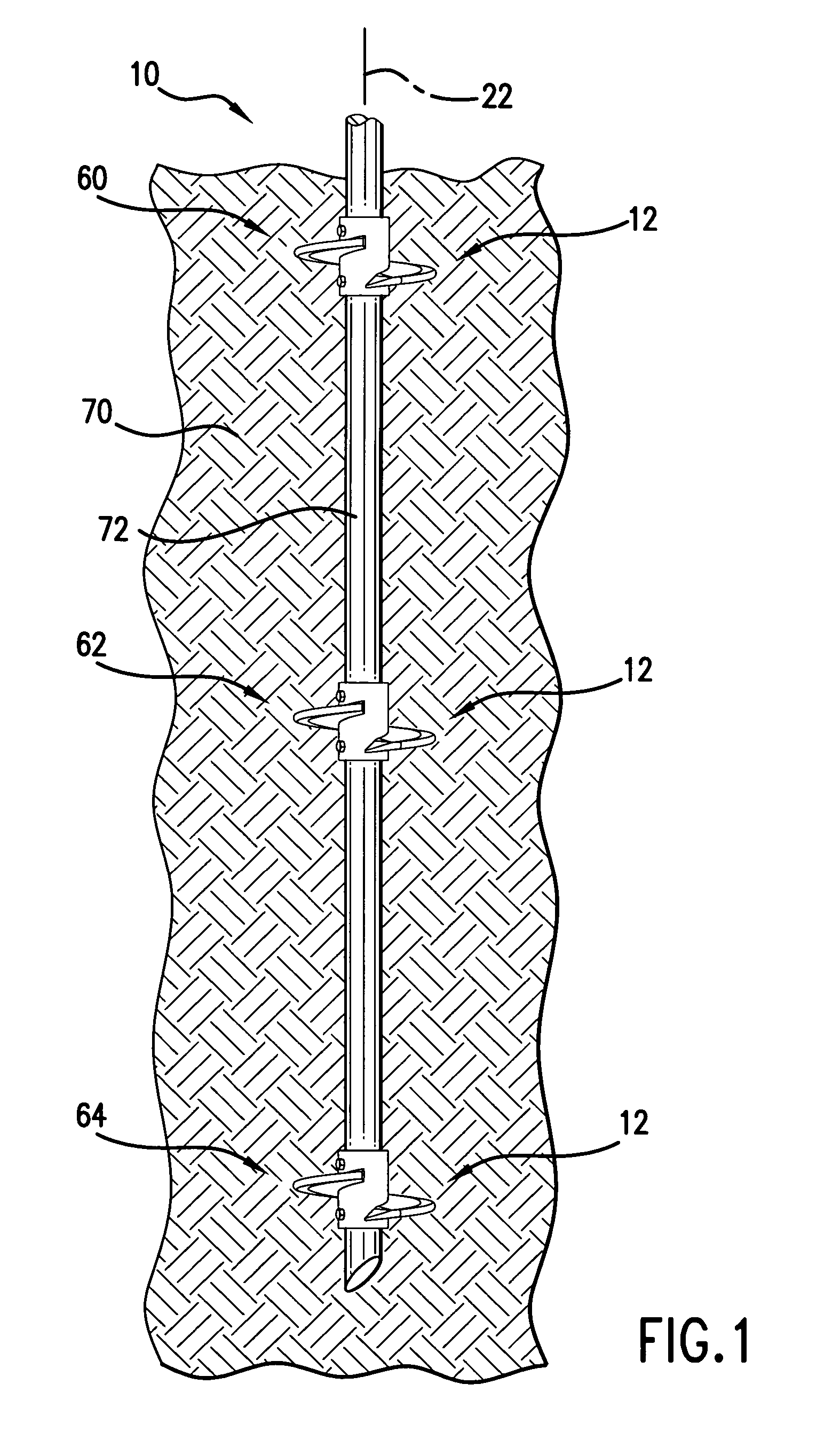
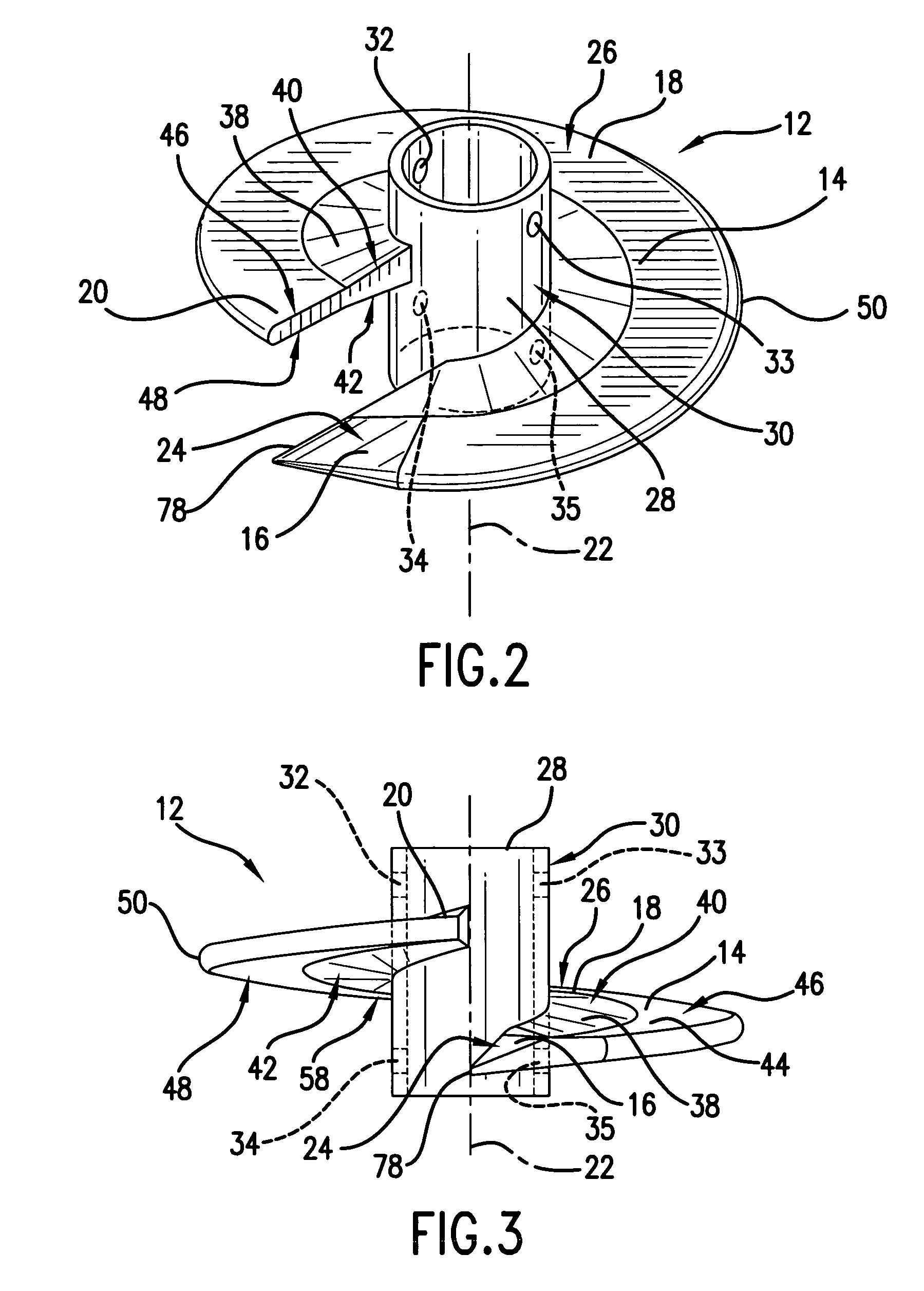
[0007]The present invention provides for a bearing plate for use in an anchor assembly. The bearing plate may be designed in order to include features that reduce the amount of friction experienced by the bearing plate during insertion so as to result in a more accurate calculation of the resulting bearing capacity of the anchor assembly. Additional features of the bearing plate may be provided in order to increase the strength of the bearing plate and ease of manufacture. Further, a method of forming an anchor assembly is provided that allows for the number, spacing, or type of bearing plate to be adjusted in the field so that an anchor assembly with a different bearing capacity can be realized.

Problems solved by technology

It is sometimes the case that soil properties at a construction site are not sufficiently stable to allow a structure to be built.
Further, currently built structures sometimes become cracked, experience partial collapse, or are otherwise damaged due to unstable soil conditions beneath the structure.
It is sometimes the case that undesirable friction is created between the bearing plate and the ground when driving the anchor assembly therein.
The bearing plate may possibly hit a rock or other obstruction during insertion that causes one or more components of the anchor assembly to break.
Unfortunately, these options are often expensive and time consuming.
Unfortunately, it is sometimes the case that during insertion of the anchor assembly it is discovered that a different anchor assembly is needed.
Additionally, other circumstances arise which prevent the use of an initially chosen anchor assembly.

Method used


Image

  • Bearing plate for use in an anchor assembly and related method
  • Bearing plate for use in an anchor assembly and related method
  • Bearing plate for use in an anchor assembly and related method

Examples


Embodiment Construction

[0036]Reference will now be made in detail to embodiments of the invention, one or more examples of which are illustrated in the drawings. Each example is provided by way of explanation of the invention, and not meant as a limitation of the invention. For example, features illustrated or described as part of one embodiment can be used with another embodiment to yield still a third embodiment. It is intended that the present invention include these and other modifications and variations.

[0037]It is to be understood that the ranges mentioned herein include all ranges located within the prescribed range. As such, all ranges mentioned herein include all sub-ranges included in the mentioned ranges. For instance, a range from 100-200 also includes ranges from 110-150, 170-190, and 153-162. Further, all limits mentioned herein include all other limits included in the mentioned limits. For instance, a limit of up to 7 also includes a limit of up to 5, up to 3, and up to 4.5.

[0038]The presen...


PUM


Abstract

A bearing plate for use in an anchor assembly and associated method are provided. The bearing plate may have a body with a middle portion with a helical configuration about an axis. Leading and trailing portions are also included on either end of the middle portion. An upper leading portion surface may extend an angular distance from 5° to 45° about the axis. The upper leading and middle portion surfaces may extend at different rates in the axial direction per extension about the axis in order to reduce friction on the leading portion during insertion. Additionally or alternatively, the middle portion of the body may be tapered and / or included a rounded outer edge in order to reduce friction during insertion and / or to increase ease of manufacture. A method of putting together an anchor assembly in the field in order to achieve a desired bearing capacity is also disclosed.

Description

FIELD OF THE INVENTION[0001]The present invention relates generally to bearing plates for anchor assemblies that are used to provide support to a structure. More particularly, the present application involves a bearing plate of improved construction that experiences reduced frictional resistance upon insertion. Also, a method of forming an anchor assembly is provided.BACKGROUND[0002]It is sometimes the case that soil properties at a construction site are not sufficiently stable to allow a structure to be built. Further, currently built structures sometimes become cracked, experience partial collapse, or are otherwise damaged due to unstable soil conditions beneath the structure. Anchor assemblies are used in order to provide structural support to building foundations, retaining walls, oil and gas pipelines, utility towers, and other structures in both new and current construction. Anchor assemblies include a shaft that carries one or more bearing plates that are generally arranged i...

Claims


Application Information

Patent Timeline
Patent Type & Authority Patents(United States)
IPC IPC(8): E02D5/56
CPCE02D5/801E02D5/80
Inventor GANTT, JR., W. ALLEN
Owner INDEPENDENCE MATERIALS GRP LLC
Why Eureka
Try Eureka