Method of using adjustable pivotal wrench

a technology of pivotal wrench and wrench handle, which is applied in the direction of wrenches, screwdrivers, manufacturing tools, etc., can solve the problem of inherently and achieve the effect of reducing the mechanical advantage of the lever arm and more rapid rotation of the wheel operator

Inactive Publication Date: 2009-12-29
ALVARADO GABRIEL
View PDF27 Cites 13 Cited by
  • Summary
  • Abstract
  • Description
  • Claims
  • Application Information

AI Technical Summary

Benefits of technology

[0006]In this invention, a wrench is provided with a handle having a pivoted joint. In one angular position of the handle, the wrench provides a maximum lever arm to initiate rotation of the wheel operator. When the valve operator beings to turn, the handle is manipulated to a different angular position to allow more rapid rotation of the wheel operator. This inherently decreases the mechanical advantage of the lever arm.
[0007]This invention accordingly eliminates the lifting up and removal of the valve wrench at the end of the initial turn and instead allows the operator to continue rotation of the valve wheel. This is accomplished by pivoting the handle in a desired direction so movement of the valve wheel is started with a maximum length lever arm provided by the wrench. After the valve wheel is initially moved and movement of the valve wheel becomes easier, the wrench handle is pivoted in a manner that allows continuous rotation of the valve wheel until either the open or closed position is reached. The elimination of stopping rotation, lifting the wrench off the valve wheel, replacing the valve wrench on the valve wheel and rotating the valve wheel again makes this invention efficient and productive.
[0008]Thus, the wrench of this invention differs from a conventional pipe wrench by the dual action of the handle provided by a pivot pin that changes the lever arm of the wrench from a maximum length needed to start rotation of the valve wheel and a shorter length allowing continuous rotation of the valve wrench.
[0009]Another important feature of this invention is a handle on the wrench that is rotatable. When the user pivots the wrench handle to the faster speed, lower torque position and rotates the valve wheel operator, the rotatable handle allows rapid rotation with no relative movement between the handle and the user's hand.
[0012]A further object of this invention is to provide a valve wrench having an adjustable handle providing a maximum lever arm for maximum torque and a shorter handle allowing continuous rotation of the valve wheel.

Problems solved by technology

This inherently decreases the mechanical advantage of the lever arm.

Method used


Image

  • Method of using adjustable pivotal wrench
  • Method of using adjustable pivotal wrench
  • Method of using adjustable pivotal wrench

Examples


Embodiment Construction

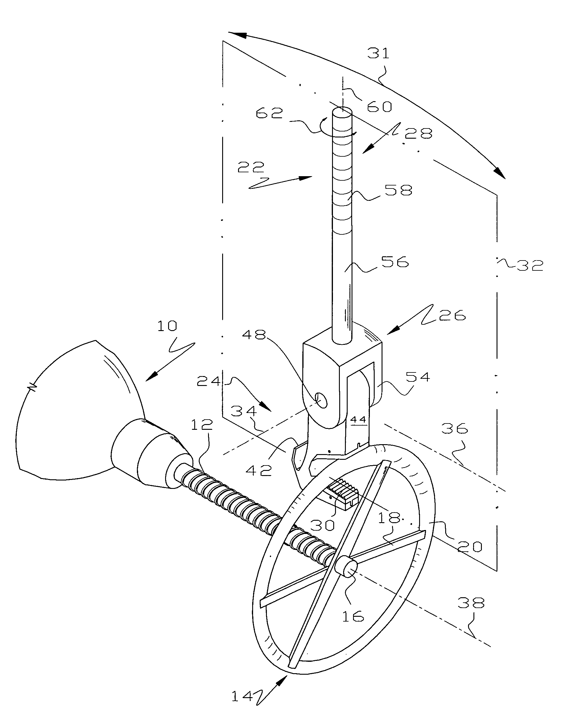
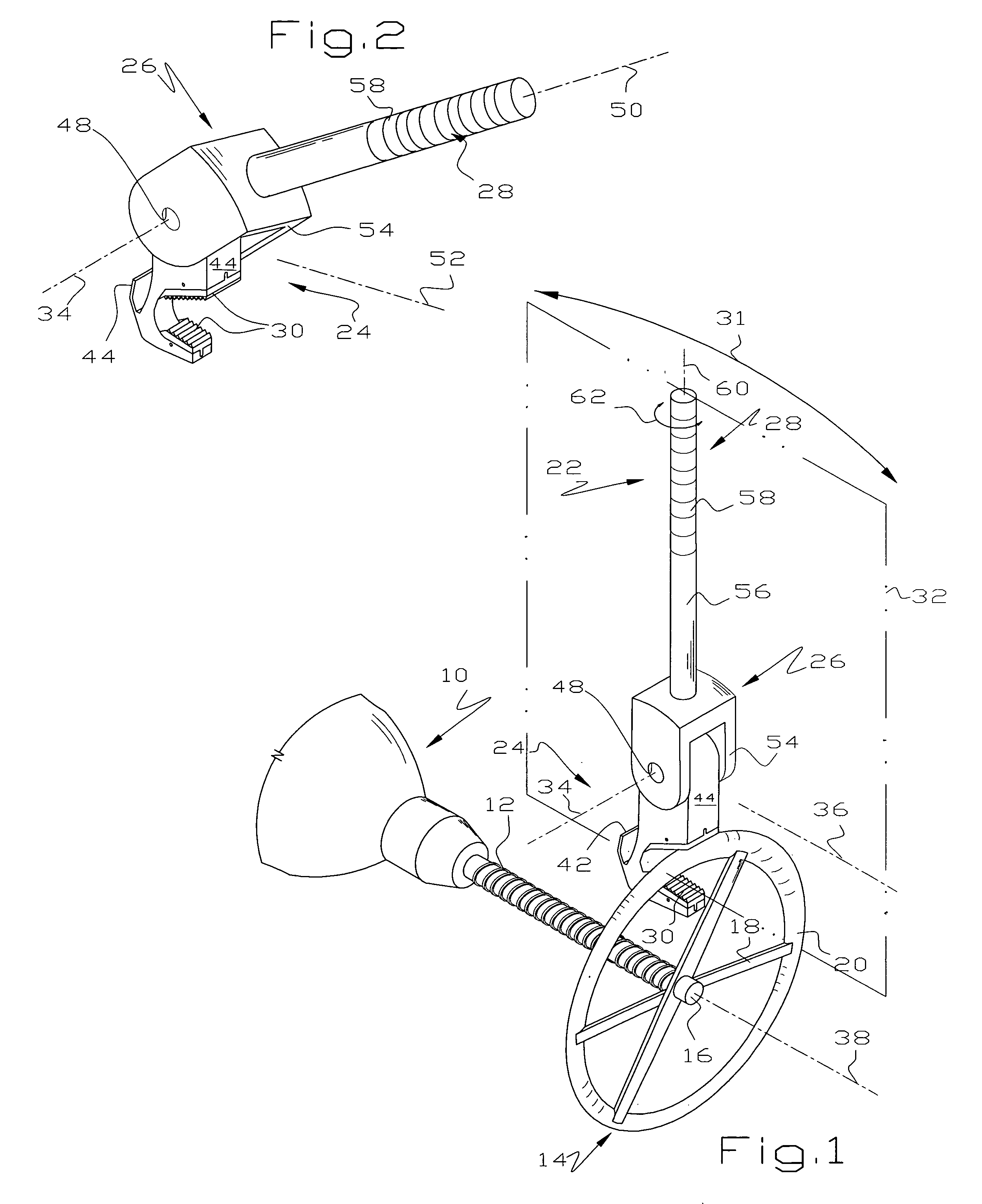
[0023]Referring to FIGS. 1 and 2, a conventional valve 10 includes a shaft or stem 12 which, when turned, moves a valve element (not shown) inside the valve 10 between open and closed positions. A conventional operator wheel 14 is attached to the shaft 12 in any suitable manner and includes a hub 16 and a plurality of spokes 18 connected to a circular rim 20 which is typically, but not universally, of circular cross section. It will be seen that the valve wheel 14 is generally planar and is perpendicular to its axis of rotation provided by the valve stem 12. Those skilled in the art will recognize the valve 10 as being typical of large valves used in refineries, chemical plants, pipelines and the like. Many valves 10 are located adjacent other equipment, pipelines or the like so that turning the wheel 14 with a conventional wrench often results in the wrench striking an adjacent object thereby limiting rotation of the wrench when applied to the wheel 14.

[0024]A wrench 22 of this inv...


PUM


Abstract

In one embodiment, a specialty wrench has a handle that is movable from a first position where the wrench acts as a conventional pipe or Stillson wrench and a second position where the handle is inclined, perhaps as much as 90°. The wrench can be used to start rotation of a valve wheel. After the valve wheel has been broken or started, the wrench handle is pivoted to a position where the valve wheel may be continuously rotated to either its open or closed position. In another embodiment, the jaw end of the wrench is angularly adjustable about a longitudinal axis so the wrench has another mode of operation, i.e. where the wrench may be used on conventional threaded connections.

Description

[0001]This application is based on Provisional Application Ser. No. 60 / 897,470 filed on Jan. 26, 2007 from which priority is claimed.[0002]This invention relates to a wrench and more particularly to a wrench having a pivoted handle to change the mechanical advantage of the wrench.BACKGROUND OF THE INVENTION[0003]Large valves often have a substantial sized wheel that is turned to open or close the valve. Sometimes, these valves are so hard to turn that a wrench is needed to turn them. Conventionally, an adjustable pipe wrench, often called a Stillson wrench, is used to turn the wheel operators of large valves. In the alternative, a fixed jaw wrench is often used to turn the wheel operators of large valves.[0004]When using a conventional pipe wrench, having either fixed or adjustable jaws, to open or close a wheeled valve operator, a series of repeated actions are necessary: engage the wrench on the perimeter of the wheel, turn the wheel in either the clockwise or counterclockwise dir...

Claims


Application Information

Patent Timeline
Patent Type & Authority Patents(United States)
IPC IPC(8): B25B13/00B25B23/16
CPCB25B13/50B25G1/063B25B23/0028
Inventor ALVARADO, GABRIEL
Owner ALVARADO GABRIEL
Why Eureka
Try Eureka