Shuttle valve

a valve and valve port technology, applied in the field of valves, can solve the problems of caregiver error risk, inconvenient process and time-consuming, caregiver error, etc., and achieve the effect of preventing the caregiver from slipping and sliding, and preventing the caregiver from sliding and sliding

Inactive Publication Date: 2009-12-29
SMITHS MEDICAL ASD INC
View PDF38 Cites 39 Cited by
  • Summary
  • Abstract
  • Description
  • Claims
  • Application Information

AI Technical Summary

Benefits of technology

[0004]In response to the foregoing problems associated with valves requiring active selection by a caregiver of the desired port coupling, the present invention provide a shuttle valve that passively and reliably selects the ports to be fluidicly coupled. This is advantageously accomplished according to the principles of the present invention by coupling a first check valve to an inlet port of the shuttle valve in a manner to permit fluid flow through the inlet port into a chamber defined by a body of the shuttle valve and to prevent fluid from discharging from the chamber through the inlet port, and by coupling a second check valve to the outlet port in a manner to per

Problems solved by technology

If the valve and the syringe are not in close proximity to one another, this process is inconvenient and time consuming for the caregiver.
There is also the risk of error by the ca

Method used


Image

  • Shuttle valve
  • Shuttle valve
  • Shuttle valve

Examples


first embodiment

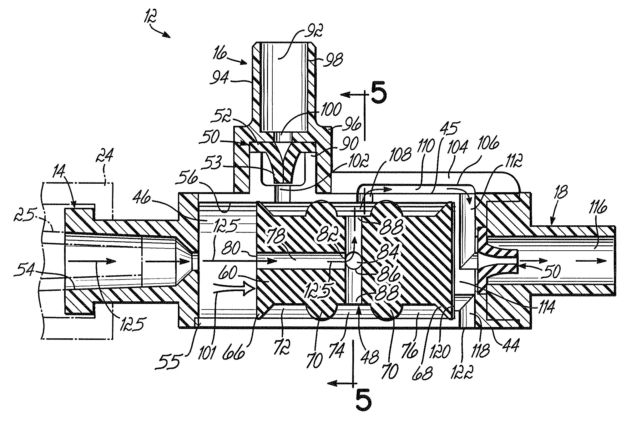
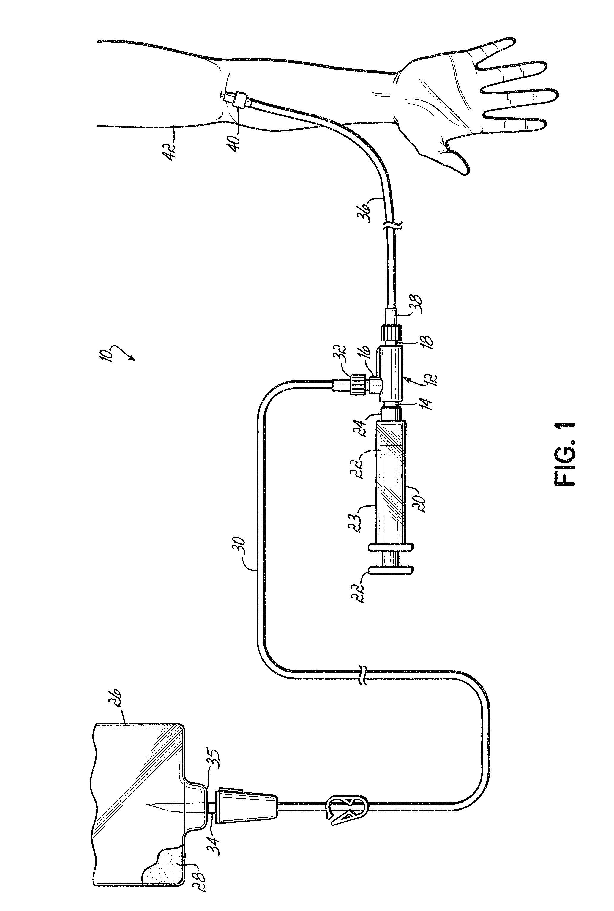
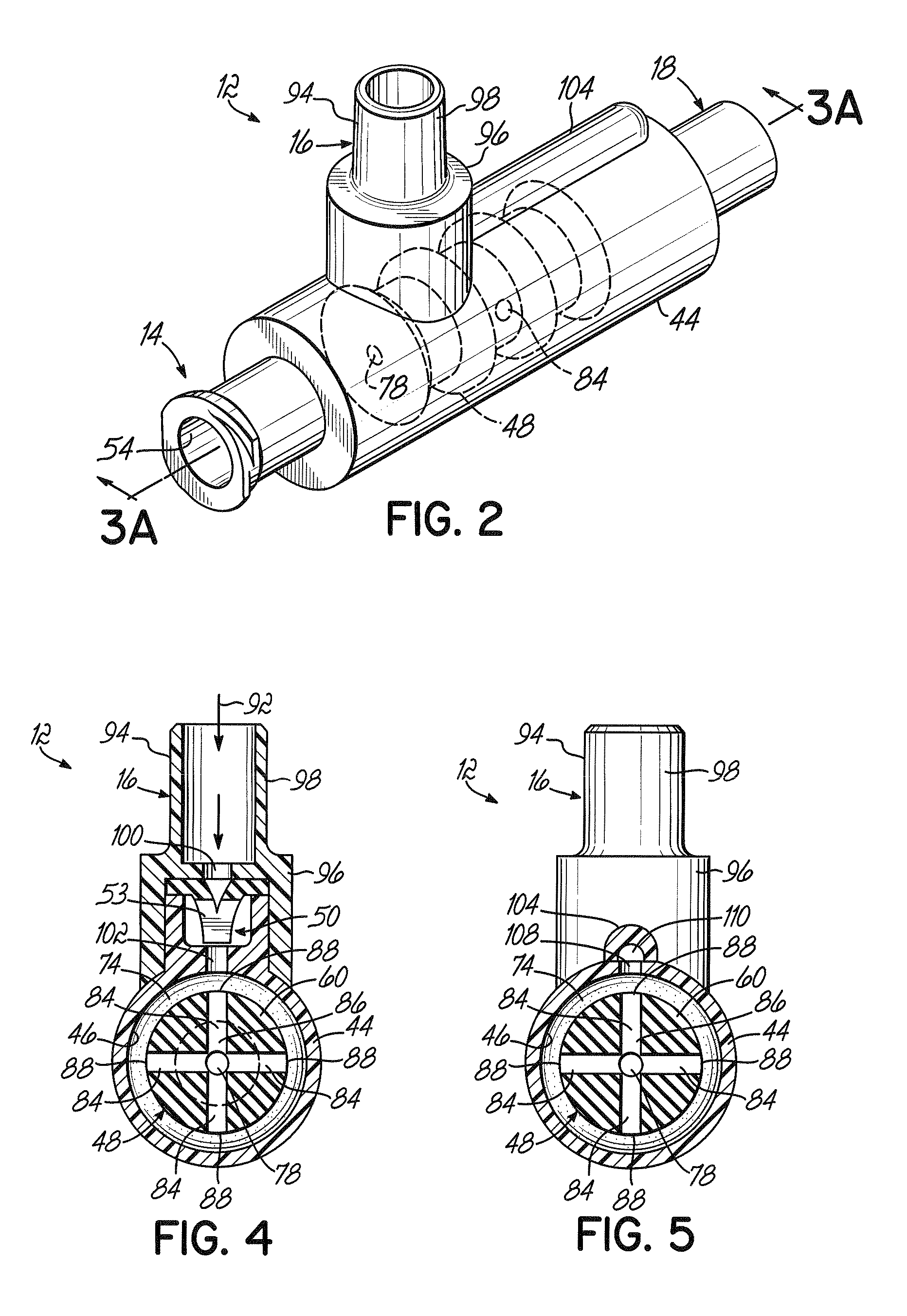
[0022]Referring now the drawings, FIG. 1 illustrates a system 10 for dispensing medical fluids intravenously to a patient, with system 10 incorporating a shuttle valve 12 according to the present invention. The shuttle valve 12 includes a common port 14, an inlet port 16 and an outlet port 18. The fluid dispensing system 10 further includes a syringe 20 coupled to the common port 14. The syringe 20 includes a plunger 22 translatable within a barrel 23 integral at the outlet end with a collar 24 coupled to the common port 14 as subsequently discussed in greater detail.

[0023]System 10 further includes a source of fluid to be dispensed which can comprise a bag 26, commonly referred to as an IV bag, containing a fluid 28 therein. The fluid 28 can comprise a variety of medications and can also include other fluids, such as saline solution, as is known in the art. The system 10 further includes a first section of tubing 30 that can comprise a single piece of tubing or multiple pieces of i...

second embodiment

[0041]FIGS. 6A, 6B and 7 illustrate a shuttle valve 150 according to the present invention. Shuttle valve 150 includes a body 152 defining an interior chamber 154, and also includes a common port 156, an inlet port 158 and an outlet port 160. Each of the ports 156, 158 and 160 are coupled to body 152. Shuttle valve 150 further includes a shuttle 162 translatably disposed within the chamber 154 between a first position shown in FIG. 6A, where the inlet port 158 and the common port 156 are fluidicly coupled and the common port 156 and the outlet port 160 are fluidicly uncoupled, and a second position shown in FIG. 6B, where the outlet port 160 and the common port 156 are fluidicly coupled and the common port 156 and the inlet port 158 are fluidicly uncoupled. The inlet port 158 and the outlet port 160 are fluidicly uncoupled in both positions of shuttle 162.

[0042]The shuttle valve 150 further includes a pair of the check valves 50 discussed previously with respect to shuttle valve 12....

third embodiment

[0051]FIGS. 8A and 8B illustrate a shuttle valve 230 according to the present invention. Shuttle valve 230 includes a body 232 defining an interior chamber 234, and also includes a common port 236, an inlet port 238 and an outlet port 240. Each of the ports 236, 238 and 240 is coupled to body 232. The shuttle valve 230 further includes a shuttle 242 translatably disposed within the chamber 234 between a first position shown in FIG. 8A, wherein the inlet port 238 and the common port 236 are fluidicly coupled and the common port 236 and the outlet port 240 are fluidicly uncoupled, and a second position shown in FIG. 8B, wherein the outlet port 240 and the common port 236 are fluidicly coupled and the common port 236 and the inlet port 238 are fluidicly uncoupled.

[0052]Shuttle valve 230 also includes a pair of the check valves 50 discussed with respect to previous embodiments of the present invention. A first one of the check valves 50 is coupled to the inlet port 238 in a manner to pe...


PUM


Abstract

A shuttle valve (12,150,230) is provided having a body (44,152,232) defining an interior chamber (46,154,234). The valve (12,150,230) includes inlet (16,158,238), outlet (18,160,240) and common (14,156,236) ports that are coupled to the body (44,152,232). A shuttle (48, 162,242) is translatably disposed within the chamber (46,154,234) between a first position wherein the inlet (16,158,238) and common (14,156,236) ports are fluidicly coupled and the common (14,156,236) and outlet (18,160,240) ports are fluidicly uncoupled, and a second position wherein the outlet (18,160,240) and common (14,156,236) ports are fluidicly coupled and the common (14,156,236) and inlet (16,158,238) ports are fluidicly uncoupled. A first check valve (50,50,50) coupled to the inlet port (16,158,238) to permit fluid flow through the inlet port (16,158,238) into the chamber (46,154,234) and to prevent fluid from discharging therethrough. A second check valve (50,50,50) is coupled to the outlet port (18,160,240) in a manner to permit fluid to discharge from the chamber (46,154,234) through the outlet port (18,160,240) and to prevent fluid from flowing through the outlet port (18,160,240) into the chamber (46,154,234).

Description

FIELD OF THE INVENTION[0001]The present invention is directed to a valve and, more particularly, to a shuttle valve that can advantageously be utilized in a system for dispensing medical fluids intravenously to a patent.BACKGROUND[0002]Various systems are known in the medical arts for dispensing a variety of fluids, such as saline and medication intravenously to a patient. One known system includes a three way stopcock valve and a syringe that are manually operated by a caregiver. An inlet port of the valve is fluidicly coupled to a source of fluid, while a common port is fluidicly coupled to a syringe and an outlet port is fluidicly coupled to a patient. While systems of this general type have been successfully utilized, they are subject to some disadvantages. In the first instance, when a caregiver enters a patient's room to administer an intravenous fluid, the caregiver must first check the stopcock valve to ensure the valve position is selected to fluidicly couple the inlet and ...

Claims


Application Information

Patent Timeline
IPC IPC(8): G05D11/00F16K21/04
CPCA61M5/14216A61M39/223A61M39/24F16K31/1226F16K11/0712F16K11/0716F16K15/147A61M2039/2473A61M2039/2493A61M2039/2486Y10T137/2544Y10T137/7838
Inventor AMLEY, JOSEPH M.LINCOLN, DANNY F.
Owner SMITHS MEDICAL ASD INC
Why Eureka
Try Eureka