
Fixing device for fastening a roof box

a fixing device and roof box technology, applied in the direction of fastening means, supplementary fittings, vehicle components, etc., can solve the problems of limited load capacity of expensive stamped bent parts of hooks, and achieve the effect of facilitating the mounting of the fixing devi

Active Publication Date: 2009-12-29
THULE SWEDEN AB
View PDF18 Cites 12 Cited by
  • Summary
  • Abstract
  • Description
  • Claims
  • Application Information

AI Technical Summary

Benefits of technology

[0003]Therefore, the object of the invention is to provide a fixing device for fastening a roof box which is built so as to be sturdy and enables a reliable locking and unlocking.
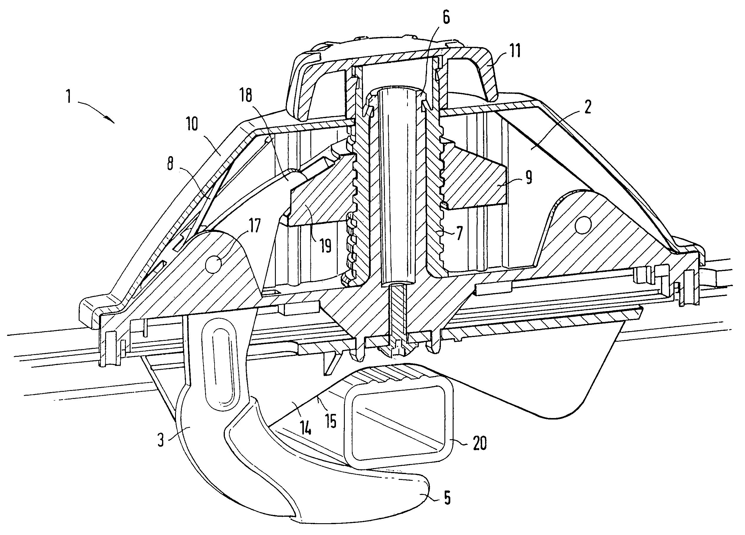
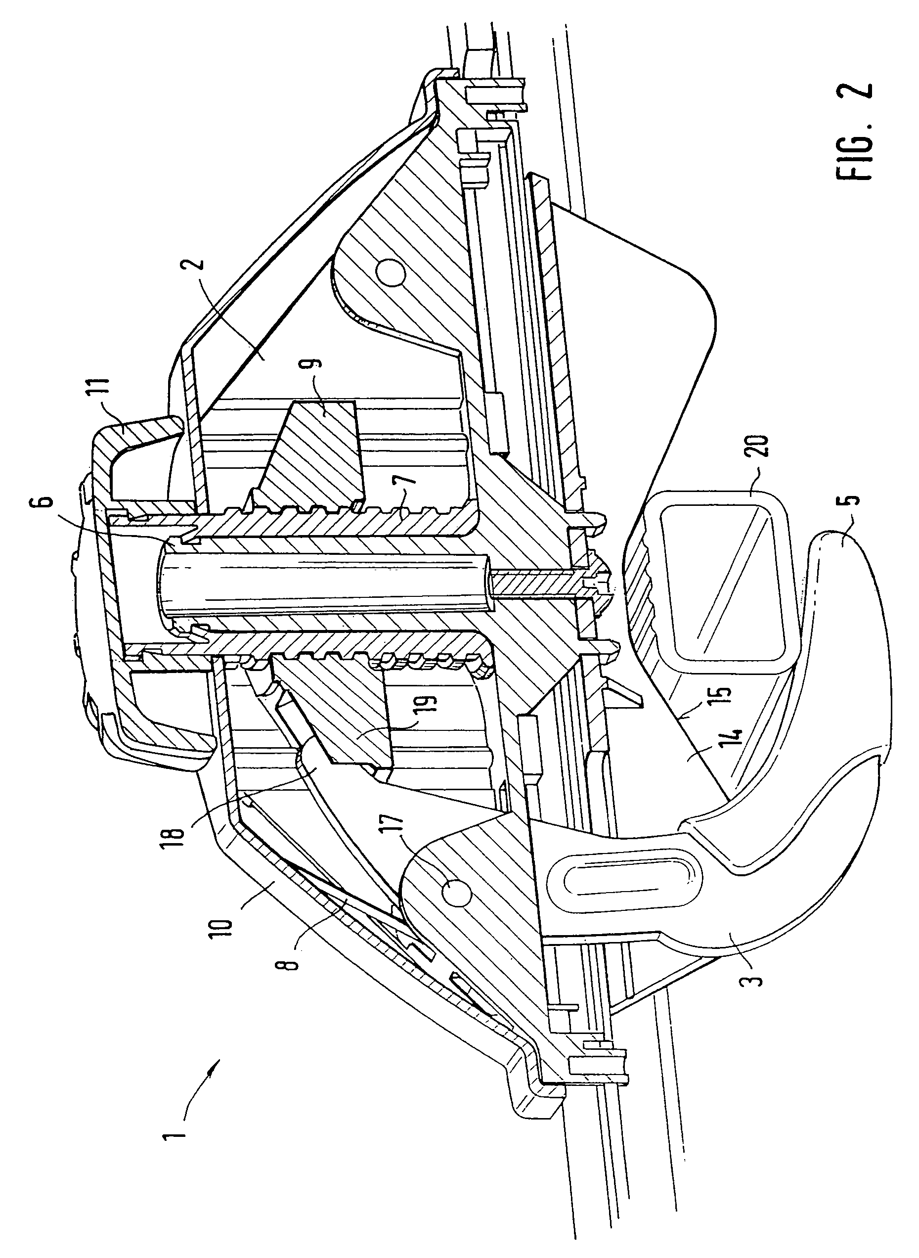
[0008]A further improvement can be obtained in that one or each clamping jaw is acted upon by a spring element which presses the interior end section of the clamping jaw against the stop element. Since the force of the spring element acts on the clamping jaw in every position, the locking and unlocking takes place free from play. The outer ends of the clamping jaws are permanently held in the open position by the spring elements, the interior end sections of the clamping jaws resting against the stop element. In this way, the clamping jaws are automatically opened as far as possible, as a result of which the mounting of the fixing device is facilitated. Preferably, the spring element is in the form of a leaf spring. The spring element can be braced on the support base or at another point as long as it is ensured that the clamping jaws are pressed against the stop element by the spring element.
[0009]It is also within the scope of the invention that the clamping jaws be provided with a lining. Preferably, this lining consists of plastic which surrounds the metal clamping jaws and protects the surface of the crossbars.
[0010]According to a further embodiment of the invention, it can be provided that the clamping jaws are arranged in parallel planes and are movable. Preferably, both clamping jaws are moved by a specific degree parallel and opposite to one another, the displacement corresponds at least to half of the thickness of the clamping jaws in each case. This makes it possible to move the clamping jaws past one another when the fixing device is being locked and to lie adjacent to one another in the locked position. In this way, the transmitted forces are distributed over both clamping jaws.

Problems solved by technology

A further disadvantage can be seen in that the hooks are expensive stamped bent parts whose load capacity is limited in wide and high roof carriers.

Method used


Image

  • Fixing device for fastening a roof box
  • Fixing device for fastening a roof box
  • Fixing device for fastening a roof box

Examples


Embodiment Construction

:

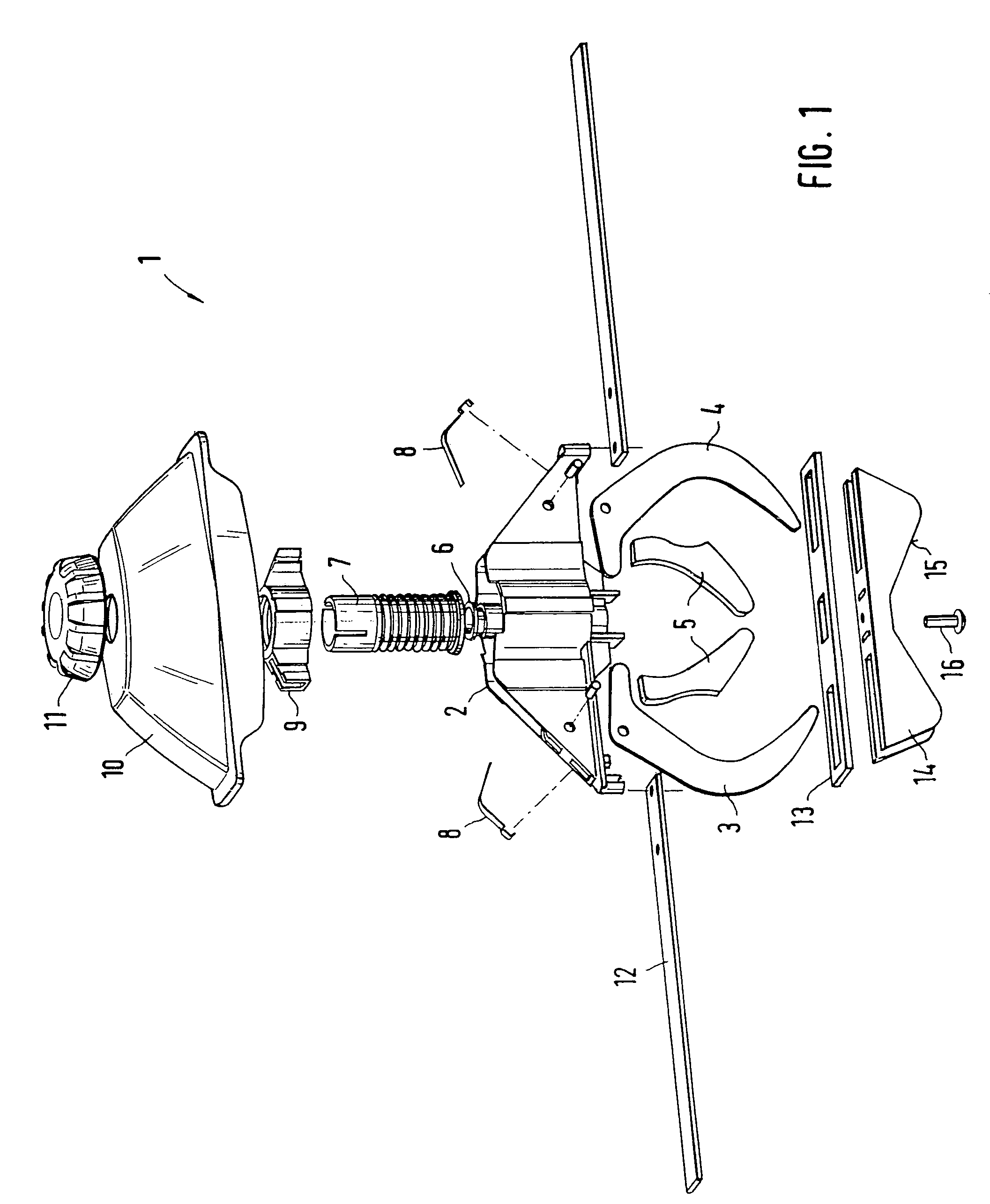
[0014]FIG. 1 an exploded drawing of an embodiment of the fixing device according to the invention;

[0015]FIG. 2 a sectional view of the fixing device of FIG. 1;

[0016]FIG. 3 a view of the essential parts of the fixing device in the unlocked position; and

[0017]FIG. 4 the fixing device shown in FIG. 3 in the locked position.

[0018]The fixing device 1 shown in FIG. 1 consists of a support base 2 on which two-armed clamping jaws 3, 4 are swivel-mounted. The clamping jaws 3, 4 are crescent-shaped and are pivoted on the support base 2 by bolts. The clamping jaws 3, 4 which are made of metal, preferably of steel, have plastic linings 5 on their ends lying outside of the roof box. The clamping jaws 3, 4 are stamped parts and can be produced in a cost-efficient manner.

[0019]The support base 2 has an essentially trapezoidal form and is made partially hollow. The central part of the support base 2 has a tubular pin 6 which is used to support a screw element 7 which is freely rotatable on the pin...


PUM


Abstract

A fixing device for fastening a roof box to crossbars fastened to a vehicle roof includes two-armed clamping jaws that extend through the bottom of the roof box and can be braced, the clamping jaws being mounted on a support base fixed in the interior of the roof box in a manner so as to pivot about a stationary swivel axis and interior end sections of the clamping jaws rest against a stop element which is vertically displaced by rotating an actuating element in order to move the clamping jaws between a locked and an unlocked position by a pure swivel motion.

Description

BACKGROUND OF THE INVENTION:[0001]The invention relates to a fixing device for fastening a roof box on crossbars which are fastened to a vehicle roof, said fixing device comprising two-armed clamping jaws that extend through the bottom of the roof box and can be braced.SUMMARY OF THE INVENTION:[0002]A fixing device for fastening a roof box to a vehicle roof is known from EP 1 338 474 A1. This device has a mounting body arranged inside the roof box which has openings for L-shaped connecting means. These connecting means are held in an actuating element which has an exterior thread which interacts with a corresponding interior thread of a control grip. Proceeding from the locked position, the actuating element screws into the control grip when the control grip is turned, as a result of which the L-shaped hooks are first of all vertically lowered. The translational motion is overlapped with a swivelling motion by the special design of the openings of the mounting body, so that the hook...

Claims


Application Information

Patent Timeline
Patent Type & Authority Patents(United States)
IPC IPC(8): B60R9/058B60R9/055F16B2/10
CPCB60R9/055F16B2/10Y10T24/44026Y10T24/44504Y10T24/44239
Inventor EMMERLING, ALEXANDERFRITSCHE, GUENTHER
Owner THULE SWEDEN AB
Learn More