XY guide table

a technology of xy guide table and xy ball, which is applied in the direction of manufacturing tools, instruments, and gearing, can solve the problems of increasing the size and weight of the xy guide table, and achieve the effect of preventing rattling of the upper plate, sufficient rigidity, and eliminating the clearance between the balls

Active Publication Date: 2009-12-29
THK CO LTD
View PDF19 Cites 18 Cited by
  • Summary
  • Abstract
  • Description
  • Claims
  • Application Information

AI Technical Summary

Benefits of technology

[0006]By selecting balls of a relatively large diameter and imparting preload to the balls rolling in the ball rolling grooves, the clearances between the balls and the ball rolling grooves are eliminated, and it is possible to prevent the above-mentioned rattling of the upper plate with respect to the lower plate. However, since the ball rolling grooves are formed in the side wall portions formed by bending through press working, selection of balls of a large diameter results in deformation of the side wall portions of the plates before the balls are brought into contact with the ball rolling grooves to be compressed, thus making it impossible to impart a sufficient preload to the balls.
[0007]Thus, it is necessary to improve the machining precision in the press working, and to enhance the rigidity of the steel plates to be formed into the above-mentioned plates. However, taking those measures will lessen advantages of press working, that is, satisfactory productivity and a low cost, resulting in an increase in a production cost of an XY guide table.Means for Solving the Problems
[0008]The present invention has been made in view of those problems. It is an object of the present invention to provide an XY guide table in which the rigidity of the portions where the ball rolling surfaces are formed is enhanced to thereby eliminate the clearances between the balls and the ball rolling grooves, making it possible to guide the upper plate in the X-direction and the Y-direction with respect to the lower plate without involving any rattling, and which can be formed in a very thin shape.
[0010]According to the above-mentioned technical means, the lower plate, which is fixed to a stationary portion, and the upper plate, which is fixed to a movable member, are both equipped with storage grooves and formed in a substantially channel-like configuration, and are stacked together such that the storage grooves are opposed to each other and orthogonal to each other, so it is possible to arrange the intermediate plate in a space defined by the storage grooves, and to enable the lower plate and the upper plate to be stacked together so as to be opposed to each other with a slight gap therebetween, thus making it possible to provide a very thin XY guide table.
[0011]Further, each of the lower plate and the upper plate is formed in the substantially channel-like configuration by arranging on both sides of the connecting plate portion the pair of rail bodies of the substantially rectangular sectional configuration, with the ball rolling groove being formed in the side surface of each rail body; by forming the mounting holes for the fastening members in the rail bodies, the lower plate can be fixed to the stationary portion through the intermediation of the rail bodies, and the upper plate can be fixed to the movable member through the intermediation of the rail bodies. Thus, it is possible to impart a sufficient level of rigidity to the portions of the lower plate and the upper plate where the ball rolling grooves are formed, to eliminate the clearances between the balls and the ball rolling grooves, and to prevent rattling of the upper plate with respect to the lower plate. In addition, it is also possible to impart preload to the balls, making it possible to guide the upper plate with respect to the lower plate with high rigidity and with high accuracy.

Problems solved by technology

However, since the rail in the Y-direction is arranged on the lower table, which is movable in the X-direction, high rigidity is required of the lower table itself; further, the height of the XY guide table as measured from the stationary portion to the upper table cannot but be rather large, resulting in an increase in the size and weight of the XY guide table.

Method used


Image

  • XY guide table
  • XY guide table
  • XY guide table

Examples


Embodiment Construction

[0024]In the following, the XY guide table of the present invention will be described in detail with reference to the accompanying drawings.

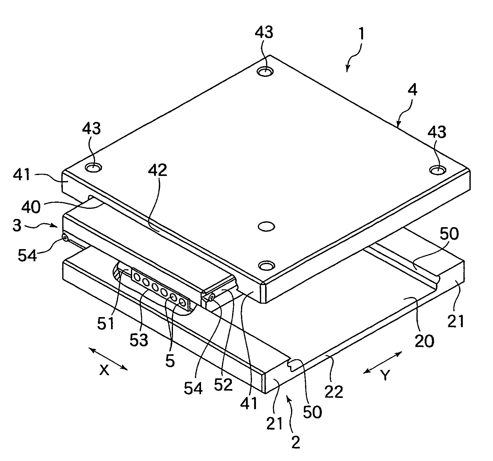
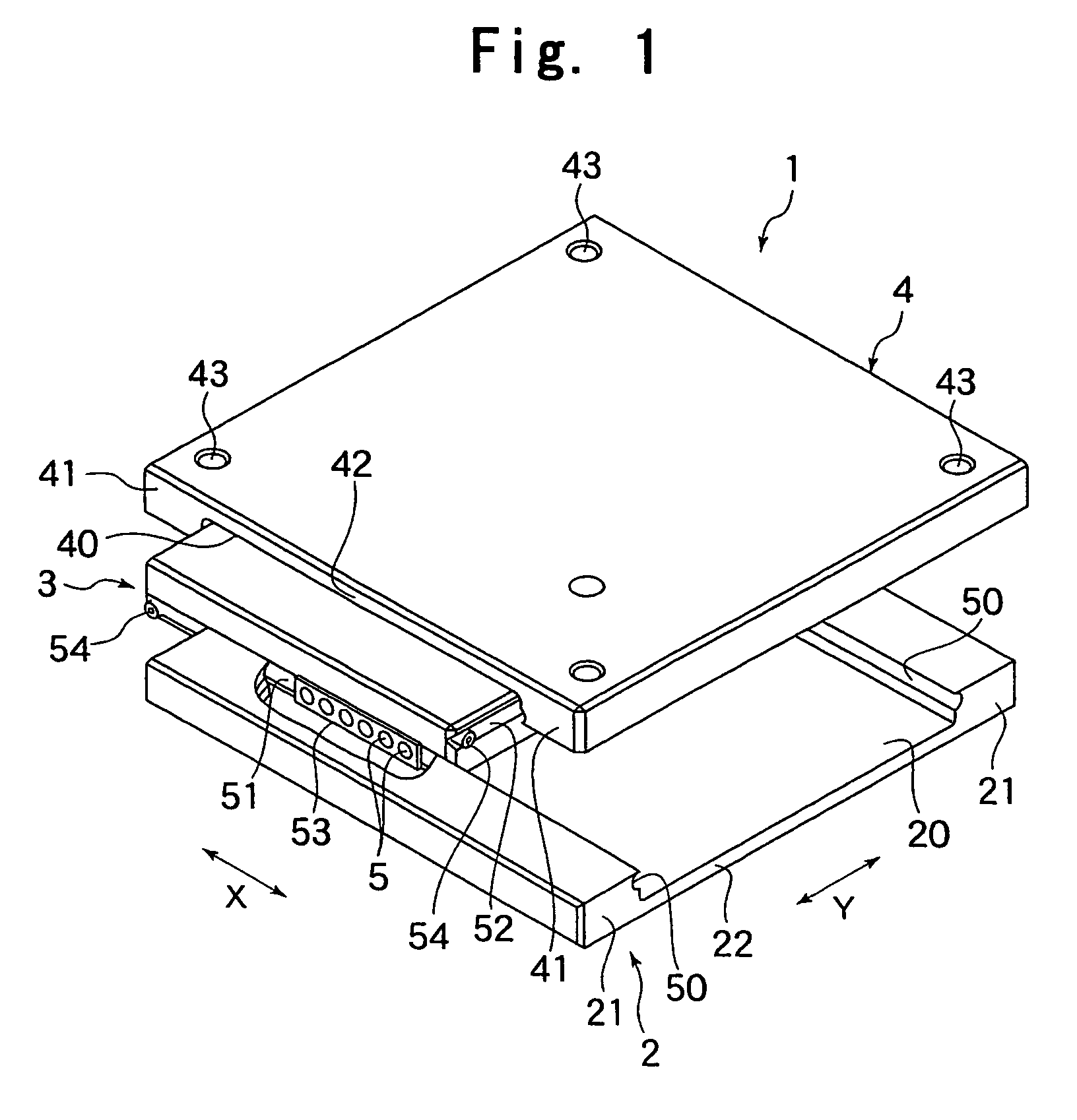
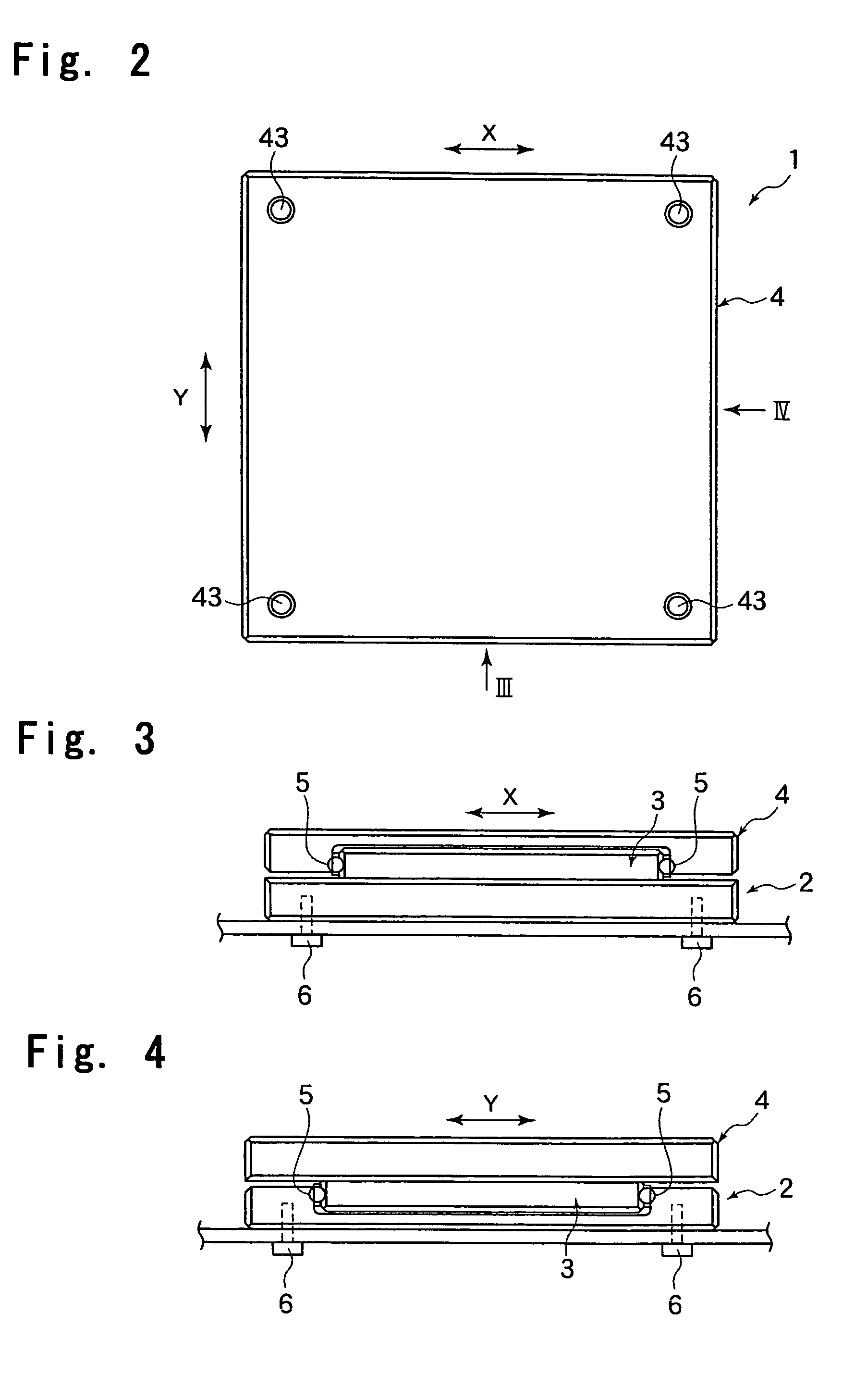
[0025]FIG. 1 is a perspective view of an XY guide table according to a first embodiment of the present invention, FIG. 2 is a plan view of this table, FIG. 3 is a view taken in a direction of an arrow III of FIG. 2, and FIG. 4 is a view taken in a direction of an arrow IV of FIG. 2.

[0026]The XY table 1 is composed of a lower plate 2 fixed to a stationary portion of a housing of a machine, a bed, etc., an intermediate plate 3 assembled to the lower plate 2 through the intermediation of a large number of balls 5, and an upper plate 4 assembled to the intermediate plate 3 through the intermediation of a large number of balls 5; the intermediate plate 3 is provided so as to be movable in an X-direction with respect to the lower plate 2, and the upper plate 4 is provided so as to be movable in a Y-direction with respect to the intermediate plate 3. T...


PUM


Abstract

Provided is an XY guide table in which rigidity of portions thereof where ball rolling surfaces are formed is enhanced to thereby eliminate clearances between balls and ball rolling grooves making it possible to guide an upper plate in an X-direction and Y-direction with respect to a lower plate without involving any rattling, and which can be formed in a very thin shape. The XY guide table includes the lower plate, an intermediate plate, and the upper plate assembled with each other through intermediation of the balls. Each of the lower plate and the upper plate has a pair of rail bodies of a substantially rectangular sectional configuration and a storage groove sandwiched between the rail bodies, and is formed in a substantially channel-shaped configuration. The plates are stacked together, with the storage grooves being opposed and orthogonal to each other.

Description

TECHNICAL FIELD[0001]The present invention relates to an XY guide table mounted to a stationary portion such as an apparatus housing, for freely guiding a movable member such as a product inspection stage or a machining table, in an X-direction and a Y-direction, and more particularly, to a small and high precision XY guide table suitable for small load uses.BACKGROUND ART[0002]Conventionally, a so-called built-up type XY guide table utilizing a linear guide device has been known as a device for freely moving a work table of a machine tool in the X-direction and the Y-direction, which are orthogonal to each other. More specifically, a rail is arranged on a stationary portion, such as a bed or a column, so as to extend in the X-direction, and a lower table movable along this rail is provided; further, a rail is arranged on this lower table so as to extend in the Y-direction, and an upper table movable along the rail is provided, with the upper table being freely movable in the X-dire...

Claims


Application Information

Patent Timeline
Patent Type & Authority Patents(United States)
IPC IPC(8): B23Q1/25B23Q1/62F16C29/04F16H25/22G12B5/00
CPCB23Q1/621F16C29/008F16C29/04
Inventor MUTO, KATSUYOSHI
Owner THK CO LTD
Why Eureka
Try Eureka