Femoral compression device with progressive pressure device

a compression device and progressive technology, applied in the field of femoral compression devices, can solve the problems of patient movement, change in the compression length of the pressure device, and long period, and achieve the effect of quick adjustmen

Active Publication Date: 2009-12-29
ST JUDE MEDICAL COORDINATION CENT
View PDF12 Cites 40 Cited by
  • Summary
  • Abstract
  • Description
  • Claims
  • Application Information

AI Technical Summary

Benefits of technology

[0010]The object of the present invention is therefore to provide a femoral compression device being provided with a pressuring device that allows movements by the patient without leading to a drastic change in the compression pressure applied on the femoral artery. At the sam

Problems solved by technology

As indicated above, especially the post-compression period can be rather lengthy, and during this post-compression period it frequently happens that the patient moves.
Such movements, either they are intentional or unintentional, will more or less unavoidably lead to a change in the compression length of the pressure device and therefore to a change in the compression pressure applied, which, in turn, can lead to unnecessary bleeding.
However, to use a coil spring characteriz

Method used


Image

  • Femoral compression device with progressive pressure device
  • Femoral compression device with progressive pressure device
  • Femoral compression device with progressive pressure device

Examples


first embodiment

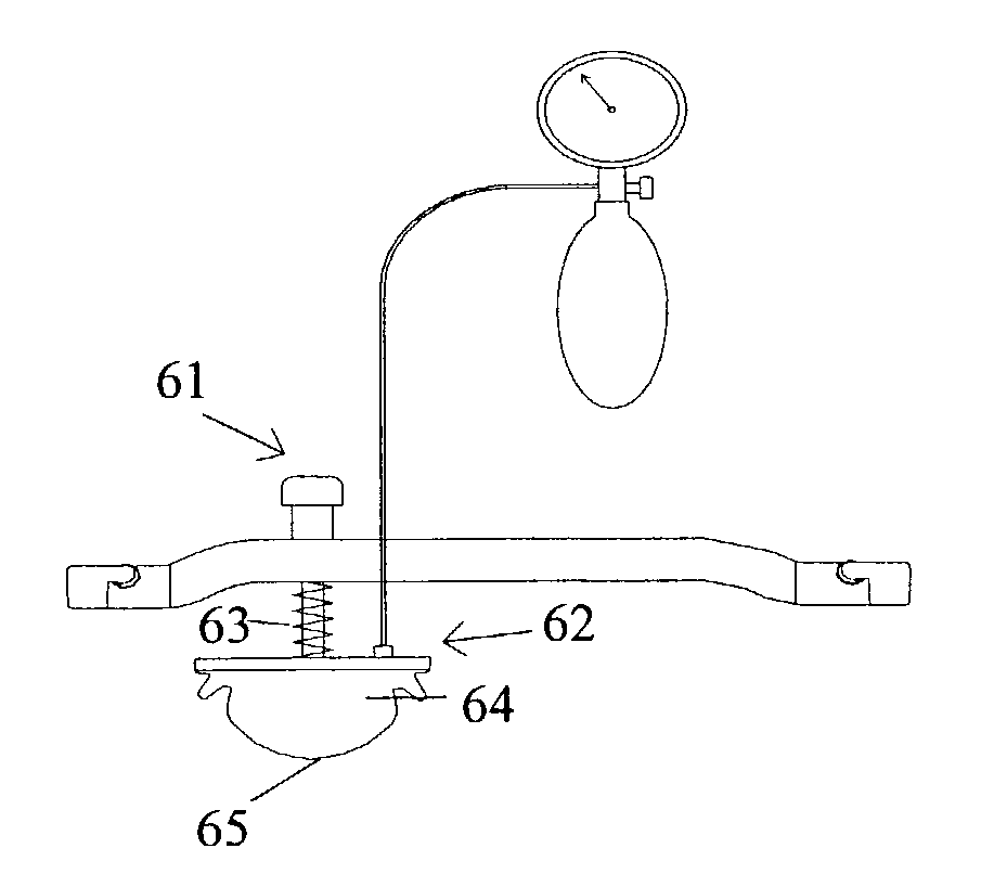
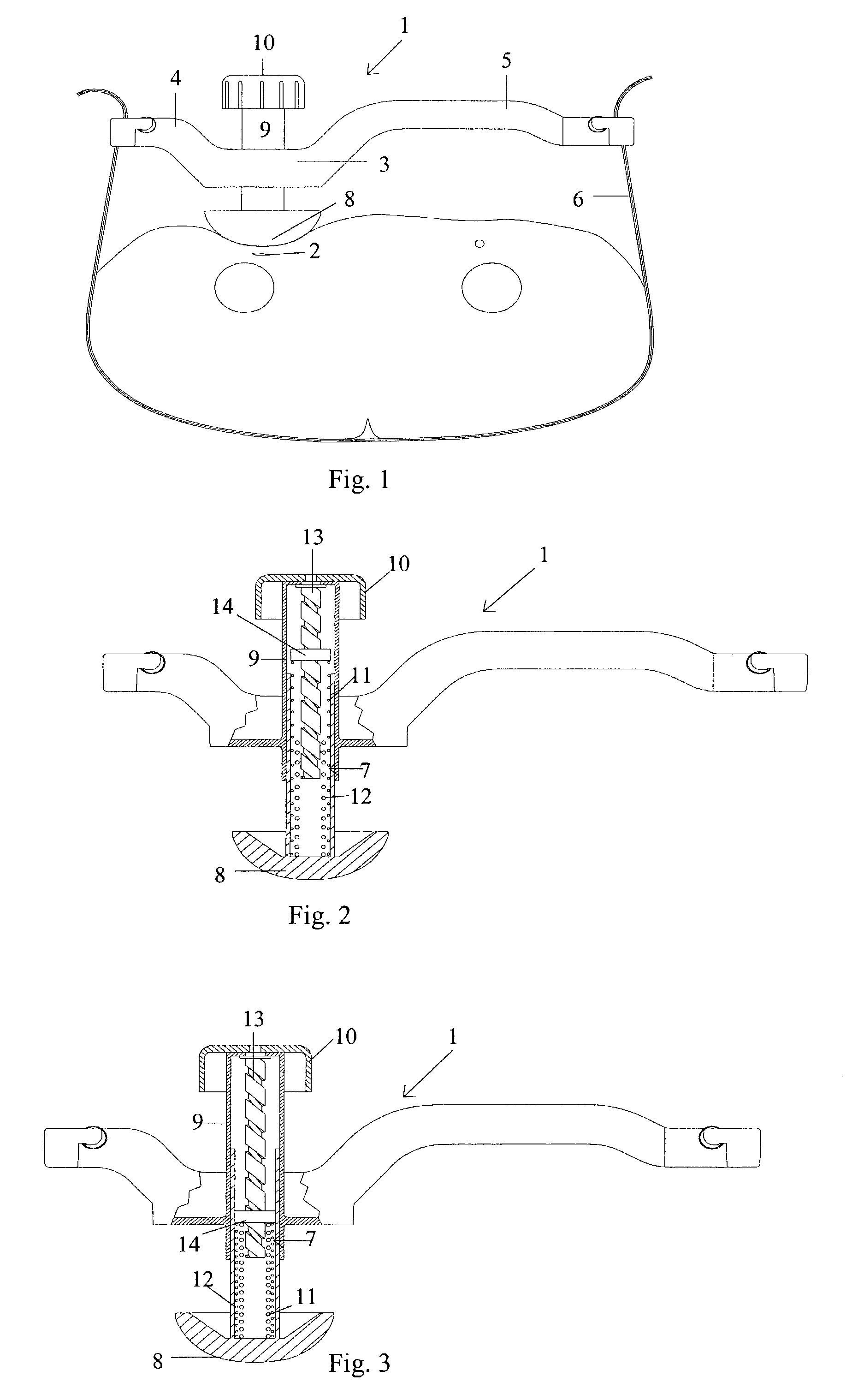
[0021]FIG. 2 is a cross-section of the pressure device 7 of the compression device 1 illustrated in FIG. 1. Although somewhat difficult to discern from FIG. 2, the pressure device 7 is in this first embodiment of the present invention in the form of two coil springs 11 and 12. The first coil spring 11 has a first length and is characterized by a first spring constant, while the second coil spring 12 has a second length and is characterized by a second spring constant. In this specific embodiment, the first length is longer than the second length and the first spring constant is smaller than the second spring constant. The first and second coil springs 11, 12 are arranged such that the respective lower ends of the first and second coil springs 11, 12 are attached to the compression member 8, with the second coil spring 12 being positioned inside the first coil spring 11. An adjusting screw 13, whose upper end is connected to the handle 10, is threaded through an internally-threaded w...

second embodiment

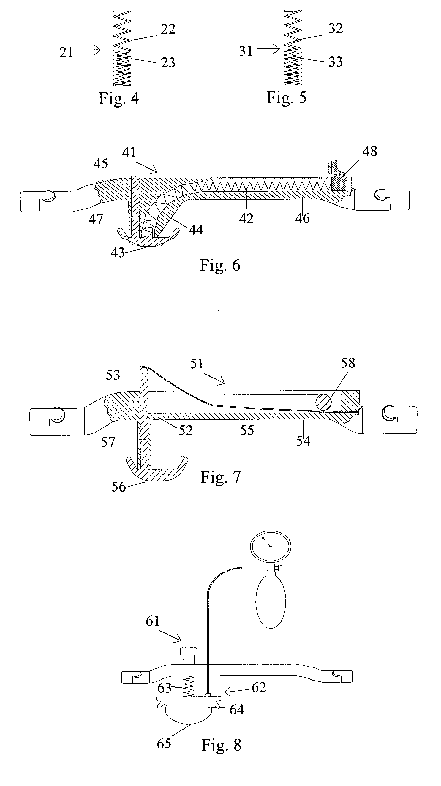
[0026]A principally somewhat different way of obtaining a non-uniform overall action for the pressure device is illustrated in FIG. 4, where a pressure device 21 comprises a first coil spring 22 being characterized by a first spring constant and a second coil spring 23 being characterized by a second spring constant. In this embodiment, one end of the first coil spring 22 is connected to one end of the second coil spring 23. With this arrangement, the overall action of the pressure device 21 is governed by both the first and second spring constants throughout the whole operating range of the pressure device 21.

third embodiment

[0027]a pressure device 31 is illustrated in FIG. 5. In this embodiment, the pressure device 31 consists of a single coil spring 31, which has two portions, a first portion 32 and a second portion 33. As can be seen in the figure, the first and second portions 32, 33 have different spring pitches, which, in turn, implies that the first and second portions 32, 33 are characterized by different spring constants. The overall action of the pressure device 31 illustrated in FIG. 5 is therefore essentially the same as the action obtained by the pressure device 21 illustrated in FIG. 4. The same effect could also be achieved by a coil spring having two coil portions with different stiffness, which could be obtained by different coil thicknesses or different materials in the different portions. In particular from FIG. 4 and FIG. 5 it should be apparent that three or more coil springs could be provided after each other, or that a single coil spring having more than two portions with differen...


PUM


Abstract

A femoral compression device (1; 41; 51; 61) for compressing a femoral artery of a patient is provided. The femoral compression device (1; 41; 51; 61) comprises a pressure device (7; 21; 31; 42; 55; 62), a compression member (8; 43; 56; 65) for compressive bearing against a puncture site, a base portion (3; 44; 52) provided with two opposing extensions (4, 5; 45, 46; 53, 54), to the ends of which a belt (6), which is adapted to be arranged around the patient's body, can be fixed. According to the invention, the pressure device (7; 21; 31; 42; 55; 62) is characterized by non-uniform overall action constants, such that when a low compression pressure is applied, the pressure device (7; 21; 31; 42; 55; 62) exhibits a small action constant, and when a high compression pressure is applied, the pressure device (7; 21; 31; 42; 55; 62) exhibits a large action constant.

Description

FIELD OF THE INVENTION[0001]The present invention relates generally to a femoral compression device comprising a pressure device that provides the pressure for compressing a femoral artery of a patient, and more particularly to a femoral compression device comprising a pressure device being characterized by having a non-uniform action over its operating range.BACKGROUND OF THE INVENTION[0002]The present invention is a modification of the femoral compression devices disclosed in the patents U.S. Pat. No. 5,307,811 and EP 0 462 088 B1, which are assigned to the present assignee and which claim priority from SE 9002077 and SE 9003271. A femoral compression device according to these publications comprises basically a pressure device for compressive bearing against a puncture site at a femoral artery of a patient (the puncture being made to access the patient's vascular system for various procedures), a belt adapted to be fixed around the patient's body, and a base plate supporting the p...

Claims


Application Information

Patent Timeline
IPC IPC(8): A61B17/00A61M29/00A61B17/132A61B19/00
CPCA61B17/1325A61B2019/465A61B2090/065
Inventor ANG.KERFELDT, DANEGNELOV, PERTENERZ, LARS
Owner ST JUDE MEDICAL COORDINATION CENT
Why Eureka
Try Eureka