Variable angle locked bone fixation system

a fixed bone and variable angle technology, applied in the field of locking bone fixation assembly, can solve the problems of cumbersome manipulation and cumbersome multi-component traditional plate assembly, and achieve the effect of simple effective and strong locking

Active Publication Date: 2009-12-29
SYNTHES USA
View PDF23 Cites 150 Cited by
  • Summary
  • Abstract
  • Description
  • Claims
  • Application Information

AI Technical Summary

Benefits of technology

[0009]Is therefore an object of the present invention to provide a simple effective and strong locking mechanism for locking the bone screw to the fixation device.
[0010]Another object of the present invention is to provide a new and novel method of fixation, having a polyaxial coupling of the screw to the fixation device, whereby a single fixation device is compatible with a wide range of screw-in angles.
[0011]Further, it is an object of the present invention to provide a method of bone fixation, which provides the surgeon with the greatest freedom to choose the most desirable angle to direct the bone screw while maintaining an effective locking mechanism.
[0012]The present invention by being an easy and straightforward procedure for the surgeon makes bone fixation simple and fast overcoming one of the most important subject of matter of actual surgery, time shortening.
[0013]By fulfilling the recently mentioned objects, the present invention is extremely helpful to the medical care area.

Problems solved by technology

These multi-component traditional plate assemblies can be cumbersome and tedious to manipulate during surgery to achieve the most desirable angle for directing the bone screw into the patient.

Method used


Image

  • Variable angle locked bone fixation system
  • Variable angle locked bone fixation system
  • Variable angle locked bone fixation system

Examples


Embodiment Construction

[0027]Hereinafter, a method of bone fixation according to the preferred embodiment of the present invention will be explained with reference to FIGS. 1-10.

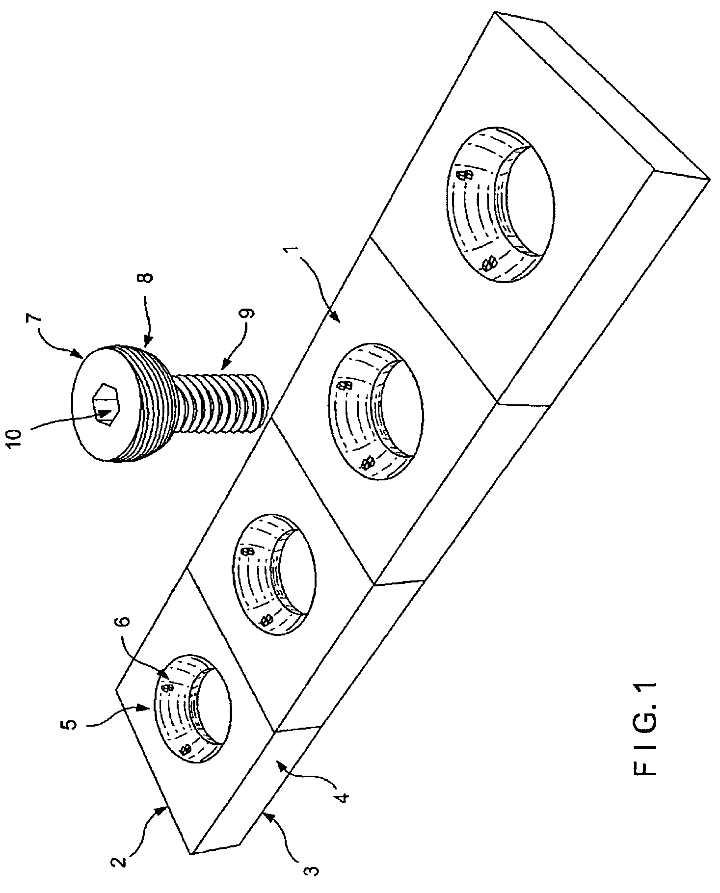
[0028]The bone plate 1 shown in FIG. 1 comprises substantially an upper side 2 and a lower side 3 intended to be closer to the bone than the upper side 2, and a number of plate holes 5 that extend from upper 2 side to lower side 3.

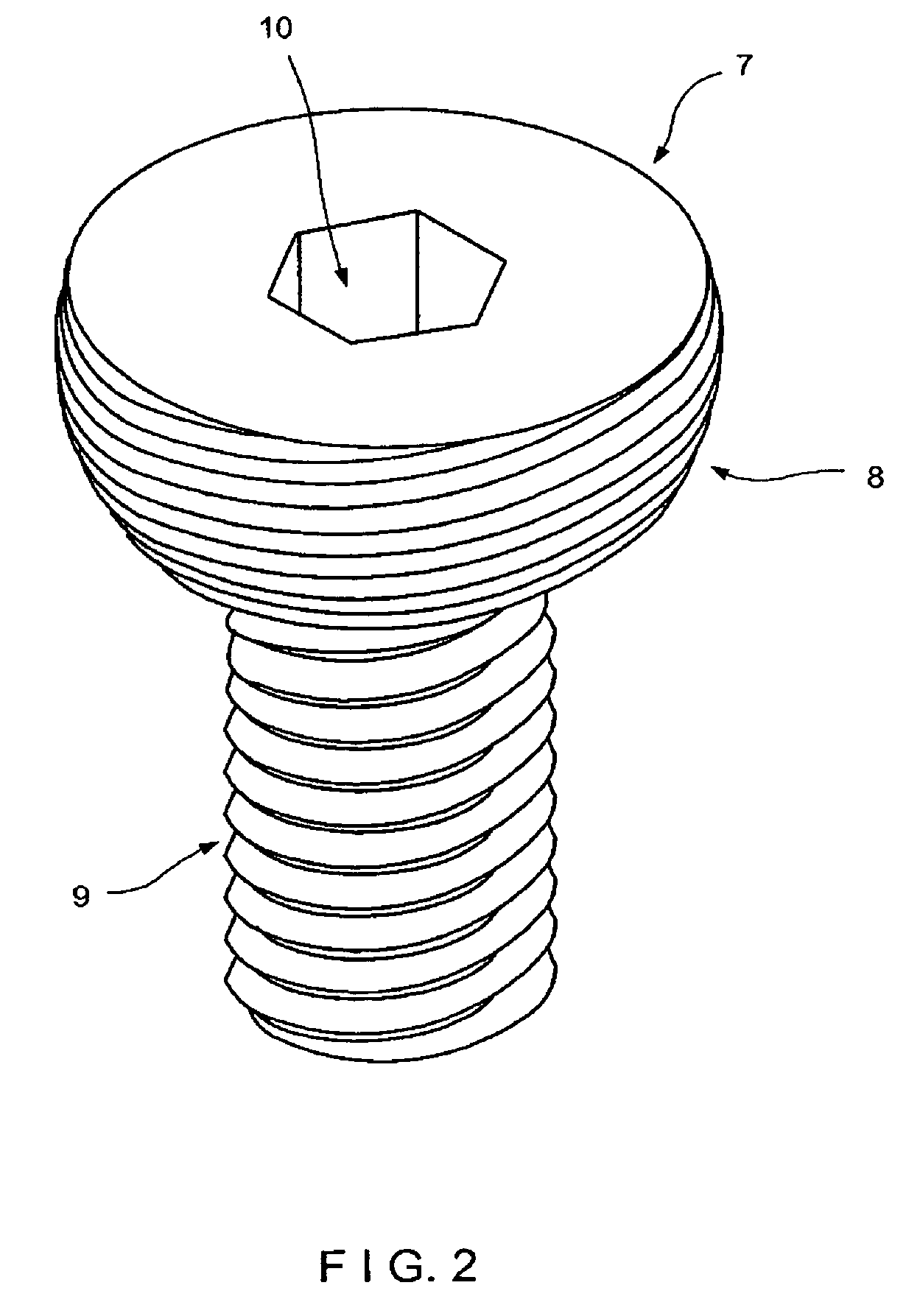
[0029]As best shown in FIG. 2, the screws 7 have a head 8 and a shank 9. The head 8 is shaped like a sphere and is threaded with a constant pitch substantially equal to the pitch of the threaded shank 9, and wherein an insertion / extraction hole 10 is cut for the connection of the insertion / extraction tool. The thread cut in the screw head 8 has a double entry, keeping substantially the same pitch of the thread of the shank 9. The thread profile may vary according to the requirements and according to the mechanical properties of the used alloy.

[0030]FIG. 3 shows a circle 11 as a projection of the sphere f...


PUM


Abstract

A bone fixation system including a fixation device having an upper surface, a lower surface and at least one opening extending therethrough and defining a first axis substantially perpendicular to the upper surface, the opening including a plurality of isolated protrusions formed on an inner surface thereof and a bone engaging member insertable through the opening at a selected angle of orientation relative to the first axis, the bone engaging member having a threaded head portion, wherein upon tightening of the bone engaging member, the threaded head portion of the bone engaging member mates with one or more protrusions of the opening to lock the bone engaging member to the plate at the selected angle of orientation relative to the first axis, and wherein the protrusions exhibit the same pitch as the threads on the bone engaging member prior to insertion of the bone engaging member in the opening.

Description

STATEMENT REGARDING FEDERALLY SPONSORED RESEARCH OR DEVELOPMENT[0001]Not applicable.REFERENCE TO SEQUENCE LISTING, A TABLE, OR A COMPUTER PROGRAM LISTING COMPACT DISC APPENDIX[0002]Not applicableBACKGROUND OF THE INVENTION[0003]The present invention is directed to a locked bone fixation assembly, and in particular to an assembly that allows for a surgeon-selected angle of the bone screw relative to the fixation device.[0004]Orthopedic fixation devices, both internal and external, are frequently coupled to bone by the use of fasteners such as screws, threaded bolts or pins. For example, bone plates can be secured to bone with bone screws, inserted through plate holes. Securing the screws to the plate provides a fixed angle relationship between the plate and screw and reduces the incidence of loosening. One method of securing the screw to the plate involves the use of so-called “expansion-head screws.” U.S. Pat. No. 4,484,570 discloses an expansion-head screw with a head that has a re...

Claims


Application Information

Patent Timeline
Patent Type & Authority Patents(United States)
IPC IPC(8): A61B17/80
CPCA61B17/8057A61B17/8047
Inventor FERNANDEZ, ALBERTO ANGEL
Owner SYNTHES USA
Why Eureka
Try Eureka