Systems and methods for modifying three dimensional geometry using an arbitrary cross-section plane

a technology of three-dimensional geometry and cross-section plane, which is applied in the field of systems and methods for modifying three-dimensional geometry using an arbitrary cross-section plane, can solve the problem that the cross-section of solids cannot be used to modify objects, and achieve the effect of avoiding the cross-section of solids

Active Publication Date: 2009-12-29
ANSYS
View PDF9 Cites 67 Cited by
  • Summary
  • Abstract
  • Description
  • Claims
  • Application Information

AI Technical Summary

Benefits of technology

[0008]Embodiments of the invention include a method for modifying the geometry data of a geometry-only format CAD object through modification of an arbitrary cross section, the CAD object being stored within a computer aided design modeling system without related history information. The method includes displaying a plurality of CAD objects, each with a corresponding position and orientation within the three dimensional modeling space of the computer aided design modeling system, and displayed within a graphical user interface of the computer aided design modeling system. The method further includes receiving, from a user of the computer aided design modeling system, the position and orientation of a cross section plane within the three dimensional modeling space of the computer aided design modeling system, the cross section plane being arbitrarily positioned relative to the orientation of one of the CAD objects, and wherein the arbitrarily positioned and oriented plane is intersecting the CAD object. The computer aided design modeling system generates a user modifiable two dimensional cross section from the intersection of the cross section plane and the CAD object, wherein the cross section plane is arbitrarily positioned and oriented relative to the CAD object, and wherein the generated two dimensional cross section comprises a plurality of user modifiable control elements. The system receives a modification to at least one of the user modifiable control elements, and makes a corresponding modification to the two dimensional cross section in response to the modification to the control element. The method also includes updating the geometry data of the CAD object such that changes to the two dimensional cross section are reflected in the updated geometry, and performing such updates without recording history information.
[0009]In other embodiments of the invention, the user modifiable control elements are comprised of a plurality of points and a plurality of lines. In yet other embodiments the geometry is updated by creating a new face based on the changes to the two dimensional cross section, and then updating the geometry data of the CAD object using the new face.

Problems solved by technology

Arbitrarily oriented and positioned cross-sections can be placed through solid objects for the purpose of viewing the geometry, but the intersection of the solid with the cross-section cannot be used to modify the object unless the cross-section is coincident with the cross section that defined the geometry in the first place.

Method used


Image

  • Systems and methods for modifying three dimensional geometry using an arbitrary cross-section plane
  • Systems and methods for modifying three dimensional geometry using an arbitrary cross-section plane
  • Systems and methods for modifying three dimensional geometry using an arbitrary cross-section plane

Examples


Embodiment Construction

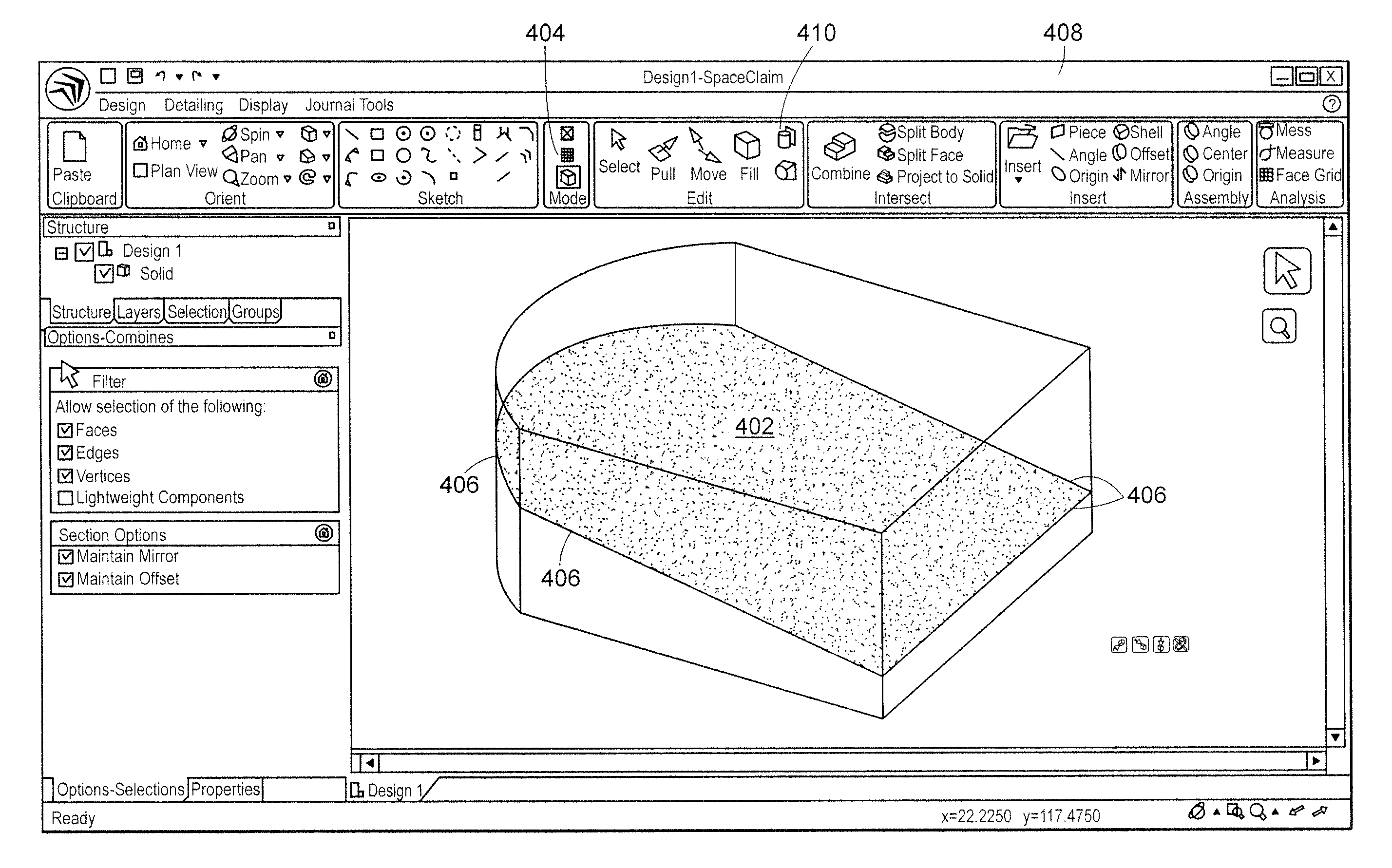
[0019]Embodiments of the invention allow any solid object or surface to be edited by any arbitrarily oriented and positioned cross-section plane that intersects the object. Solids and surfaces can be modified regardless if they were originally created in the embodiment's CAD system or if they were imported from another CAD system.

[0020]In one embodiment, a three-dimensional solid geometry modeling tool is described that can manipulate and modify 3D solids using arbitrarily oriented and positioned 2D cross-sections. The modeling tool (called section mode) allows analytic geometry (including planes, cylinders, cones, and tori) and non-analytic geometry, such as B-spline surfaces, to be manipulated using a simple mouse drag operation on the points and lines on the cross-section plane that comprise the geometry. Operations that can be performed includes moving and offsetting lines to move and offset faces, moving vertices and curves in the cross-section to rotate faces, scaling lines to...


PUM


Abstract

Embodiments of the invention comprise methods and systems for modifying the geometry data of a CAD object through modification of an arbitrary cross section, the CAD object being stored within a computer aided design modeling system. The method includes receiving, from a user the position and orientation of a cross section plane, the cross section plane being arbitrarily positioned relative to the orientation of a CAD object, and wherein the arbitrarily positioned and oriented plane is intersecting the CAD object. The CAD system generates a user modifiable two dimensional cross section from the intersection of the cross section plane and the CAD object, the cross section having a plurality user modifiable control elements. Changes to the control elements are correspondingly made to the cross section plane and the CAD object.

Description

[0001]This application is a continuation of and claims priority under 35 U.S.C. §120 to co-pending U.S. patent application Ser. No. 11 / 971,756, filed on Jan. 9, 2008, entitled Systems and Methods for Modifying Three Dimensional Geometry using an Arbitrary Cross-Section Plane, the contents of which are incorporated herein in their entirety by reference.BACKGROUND OF THE INVENTION[0002]1. Field of the Invention[0003]This invention relates to modifying the cross-sections of solid and surface geometry formed by an arbitrary intersecting plane or surface in an intuitive manner.[0004]2. Prior Art[0005]Objects in a CAD system can be represented in a parameter-based way or in a geometry-based way. In a parameter-based representation, the object is modeled as an object along with a set of features and history that define the object. In a geometry-based representation, the object is simply represented as a set of geometric data.[0006]Most modern CAD systems offer the ability to create cross-s...

Claims


Application Information

Patent Timeline
Patent Type & Authority Patents(United States)
IPC IPC(8): G09G5/00G06T17/00
CPCG06F17/5086G06T19/00G06T17/10G06T2219/008G06F30/17G09G5/00G06T15/00
Inventor DESIMONE, FRANKCOURTER, BLAKETAYLOR, DAVIDESKIN, MAXDEAN, DANIEL
Owner ANSYS
Why Eureka
Try Eureka