Method for evaluating color picture tubes and device for the same and method for making color picture tubes

a color picture tube and evaluation method technology, applied in the field of color picture tube evaluation method and device for the same, can solve the problems of time-consuming measurement using this method, insufficient data, and electron beam distortion, and achieve the effect of fast, highly reliable measurement and evaluation

Inactive Publication Date: 2009-12-29
HITACHI LTD
View PDF7 Cites 7 Cited by
  • Summary
  • Abstract
  • Description
  • Claims
  • Application Information

AI Technical Summary

Benefits of technology

[0011]The object of the present invention is to overcome the problems of the conventional technology described above and to provid

Problems solved by technology

Since the greater part of the electron beam is blocked by these, a method in which an electron beam casts a spotlight on a particular position of the picture tube display and an imaging element is used to capture an image of this spot will not provide an adequate amount of data (luminance information for multiple posit

Method used


Image

  • Method for evaluating color picture tubes and device for the same and method for making color picture tubes
  • Method for evaluating color picture tubes and device for the same and method for making color picture tubes
  • Method for evaluating color picture tubes and device for the same and method for making color picture tubes

Examples


Embodiment Construction

[0034]The following is a description of the embodiments of the present invention, with references to the drawings.

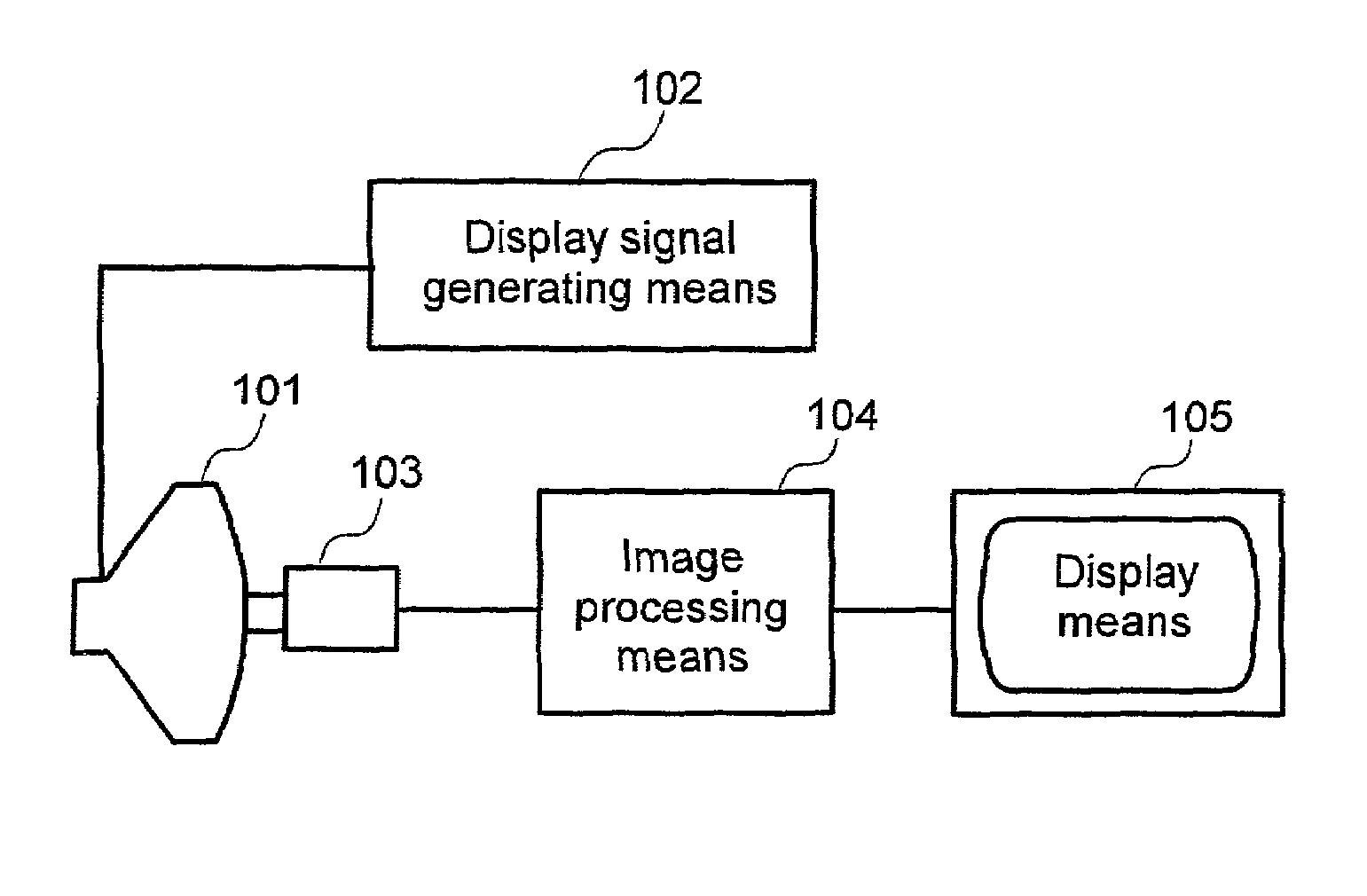
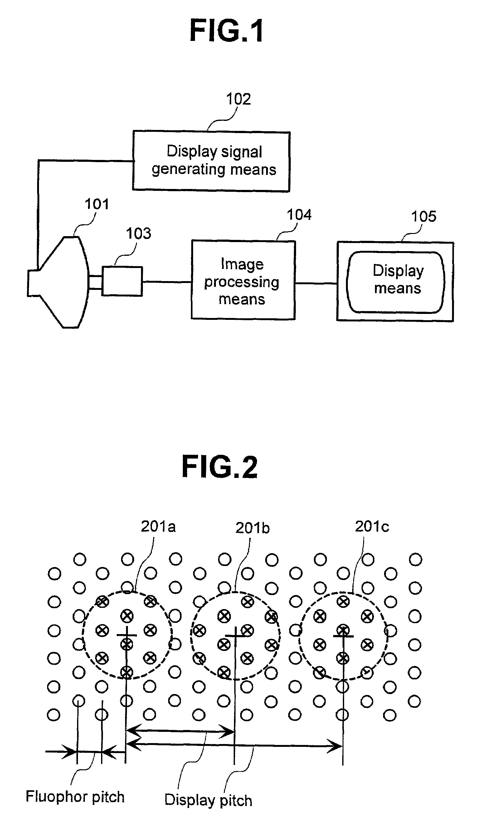
[0035]FIG. 1 shows a sample architecture of a device implementing a method for measuring electron beam intensity distribution according to the present invention.

[0036]A color picture tube 101 is the inspected object. In the following description, a shadow-mask picture tube is used as an example, but an aperture grill picture tube can be used as well. Display signal generating means 102 sends a signal to the color picture tube 101 to display a measurement pattern, designed beforehand, at a predetermined signal timing. Imaging means 103 is disposed facing the display surface of the picture tube 101 and captures an image of the displayed measurement pattern. The method used to support imaging means 103 is not shown in the figure. An operator can hold imaging means 103 or a measuring stand can be used. An imaging element that can provide two-dimensional images quickly, e.g.,...


PUM


Abstract

A method for evaluating a color picture tube includes displaying on a display surface of a color picture tube a measurement pattern including a plurality of first patterns arranged at different positions relative to fluophor dots of said color picture tube and a plurality of second patterns near said first patterns and sufficiently large relative to said fluophor dots. A first image is obtained using an imaging element to image said displayed measurement pattern. A second image is obtained using said imaging element to image while controlling light intake to allow brightness components of no more than about 1% of maximum luminance from said first image to be separated from noise and imaged. A third image is created by combining said first image and said second image while adjusting scales according to a light intake ratio. From said third image, display center positions of said plurality of first patterns is calculated using said second pattern positions. Discrete fluophor emission intensity distributions is calculated for each of said plurality of first patterns. An electron beam intensity distribution is obtained by matching display center positions of said plurality of first patterns and combining said plurality of first patterns.

Description

CROSS-REFERENCES TO RELATED APPLICATIONS[0001]This application claims priority from Japanese Patent Application No. 00-291948, filed on Sep. 21, 2000, which is incorporated by references for all purposes.BACKGROUND OF THE INVENTION[0002]The present invention relates to a method for evaluating color picture tubes and device for the same and method for making color picture tubes. The present invention seeks to provide quantitative evaluations of focus characteristics of picture tubes having color selection mechanisms.[0003]Focus characteristics of a picture tube are an important factor that affects display image quality.[0004]In the past, various devices have been proposed to automatically measure focus characteristics by measuring electron beam intensity distributions.[0005]Color picture tubes include color selection mechanisms such as shadow masks and aperture grills. Since the greater part of the electron beam is blocked by these, a method in which an electron beam casts a spotligh...

Claims


Application Information

Patent Timeline
IPC IPC(8): H04N17/02H04N3/22H01J9/42G01B11/00H04N17/04
CPCH04N17/04H01J9/42
Inventor SHIBUYA, HISAEHORIUCHI, TATSUONOZAKI, YOSHINAOYOSHIWARA, YOSHIO
Owner HITACHI LTD
Why Eureka
Try Eureka