Storage control device

a control device and storage technology, applied in the direction of record information storage, electric apparatus casings/cabinets/drawers, instruments, etc., can solve the problems of reducing the power consumption of storage control devices and the power consumption of respective magnetic disk devices forming raid groups

Inactive Publication Date: 2009-12-29
HITACHI LTD
View PDF12 Cites 21 Cited by
  • Summary
  • Abstract
  • Description
  • Claims
  • Application Information

AI Technical Summary

Benefits of technology

[0014]The first enclosure may shift a storage device that has not been accessed for a preset predetermined time or more from among the respective storage devices to a power conservation mode that suppresses power consumption.

Problems solved by technology

In the conventional technology that appears in Japanese Patent Application Laid Open No. 2001-339853, the power supply operation to the base enclosure and the power supply operation of each additional enclosure are made to work together but the results are limited from the perspective of reducing the power consumption of the storage control device.
However, in the case of the conventional technology that appears in Japanese Application Laid Open No. 2000-293314, the power consumption amount of the respective magnetic disk devices constituting the RAID group remains curtailed and there is scope for additional improvement.

Method used


Image

  • Storage control device
  • Storage control device
  • Storage control device

Examples


first embodiment

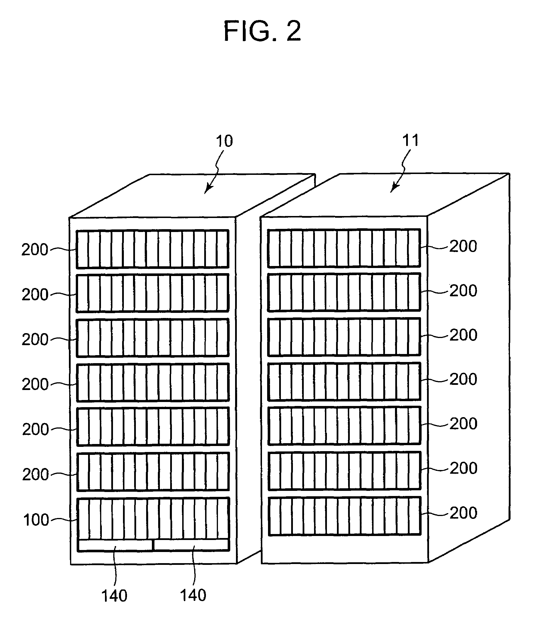
[0090]FIG. 2 is a perspective view of the external constitution of the storage control device. The storage control device is constituted by connecting a base rack 10 and an additional rack 11 by means of a cable, for example. The base rack 10 comprises a base enclosure 100 and a plurality of additional enclosures 200. The base rack 10 has the smallest constitution of the storage control device and the functions of the storage control device can be implemented using only the base rack 10. The additional rack 11 comprises a plurality of additional enclosures 200. When the storage capacity of the base rack 10 is depleted, the storage capacity can be increased by connecting the additional rack 11 to the base rack 10.

[0091]FIG. 3 is a perspective view of the base enclosure 100 as seen from the front side. A plurality of batteries 140 and a plurality of disk drives 230 are provided in the casing 101 of the base enclosure 100, at the front side 101F. The base enclosure 100 may have a const...

second embodiment

[0192]The second embodiment of the present invention will now be described on the basis of FIG. 28. Each of the following embodiments including this embodiment corresponds to a modified example of the first embodiment. In this embodiment, power supply start processing is executed only when access to the access destination drive has not been possible.

[0193]FIG. 28 is a flowchart of write processing that is executed by the controller 110 of the storage control device of this embodiment. In this flowchart, S70 to S74 correspond to S40 to S44 shown in FIG. 19. Hence, repetitive description is omitted and the description will be provided with an emphasis on the characteristics of this embodiment.

[0194]When the access destination drive is specified (S74), the controller 110 transfers write data to the additional enclosure 200 that comprises the access destination drive (S75). When it has been checked that the writing of the write data have been completed normally (S76:YES), the controller...

third embodiment

[0198]The third embodiment will be described on the basis of FIG. 29. In this embodiment, the write processing and power supply start processing shown in FIG. 19 are represented in the same flowchart.

[0199]Upon receipt of the write command from the host 13 (S200), the controller 110 stores the write data in the cache memory 114 (S201) and reports the end of processing to the host 13. The controller 110 checks the state of the access destination drive by using Table T2 (S202) and judges whether the access destination drive is running (S203).

[0200]When the access destination drive is operating (S203:YES), the processing moves to S211. When the access destination drive is not operating (S203:NO), the controller 110 judges whether the access destination drive is in the spindown state (S204). When the access destination drive is in the spindown state (S204:YES), the processing moves to S210.

[0201]When the access destination drive is not in the spindown state (S204:NO), the controller 110...


PUM

PropertyMeasurementUnit
voltagesaaaaaaaaaa
voltagesaaaaaaaaaa
timeaaaaaaaaaa

Abstract

The storage control device of the present invention reduces power consumption by stopping the flow of power to enclosures that are not being accessed. A plurality of additional enclosures are connected to a base enclosure by means of a daisy-chain connection. The respective additional enclosures are divided into three levels, namely a low usage frequency level, a medium usage frequency level, and a high usage frequency level depending on the connection distance of the additional enclosures from the base enclosure. Drives that have not been accessed for a predetermined time are spun down. When all the drives in the enclosure are in the spin down state, the supply of power from the power supply to the respective drives is stopped. Further, when the flow of power to an additional enclosure located below the enclosure itself has stopped, the switch of the latter enclosure is turned OFF and the flow of power to the additional enclosure is stopped.

Description

CROSS-REFERENCE TO RELATED APPLICATIONS[0001]This application relates to and claims priority from Japanese Patent Application No. 2006-267135 filed on Sep. 29, 2006, the entire disclosure of which is incorporated herein by reference.BACKGROUND OF THE INVENTION[0002]1. Field of the Invention[0003]The present invention relates to a storage control device.[0004]2. Description of the Related Art[0005]The storage control device comprises a storage section obtained by connected a multiplicity of hard disk drives in the form of an array and provides a host computer such as a server (‘host’ hereinbelow) with a logical storage region (logical volume). In order to improve reliability, the storage control device provides the host with a RAID (Redundant Array of Independent Disks)-based redundant storage region.[0006]Further, the data to be managed by an enterprise or the like grows day by day. Hence, a storage control device capable of increasing the storage capacity in accordance with the inc...

Claims


Application Information

Patent Timeline
Patent Type & Authority Patents(United States)
IPC IPC(8): H05K5/00G11B17/00
CPCG06F1/3221G06F1/3268G06F1/3287G06F3/0634G06F3/0689G06F3/0625Y02B60/1282Y02B60/1246Y02D10/00
Inventor HORI, MASANORISATO, MASAHIKOYAMANASHI, AKIHITO
Owner HITACHI LTD
Why Eureka
Try Eureka